Podcasting since 2005! Listen to Latest SolderSmoke

Showing posts with label ceramic resonators. Show all posts

Monday, August 8, 2022

Polyakov (RA3AAE) Direct Conversion Receiver: 40 meter DC RX with VFO at 3.5 - 3.6 MHz (with video)

I've been reading about Polyakov (or "sub-harmonic") Detectors for a long time: 

https://soldersmoke.blogspot.com/search/label/Polyakov--Vladimir

But until now, I never built one.  Recently,  Dean KK4DAS and the Vienna Wireless Makers group have been building a Direct Conversion receiver.  Their receiver uses an Si5351 as the VFO, but of course Dean and I have decided to try to do things the hard way by building non-digital VFOs.  At first we just came to the conclusion that my earlier Ceramic Resonator VFO wasn't much good (it drifted too much).  This led us into standard Colpitts and Armstrong VFOs, and the fascinating world of temperature compensation.  Then I remembered the Polyakov circuit -- this would allow us to use a 3.5 MHz VFO on the 7 MHz band.  Lower frequency VFOs are easier to stabilize, so I started building my first Polyakov receiver.  You can see the results (on 40 meters) in the video above. 

I started working with a circuit from SPRAT 110 (Spring 2002). Rudi Burse DK2RS built a Polyakov receiver for 80 and 40 that he called the Lauser Plus.  (Lauser means "young rascal" or "imp" in German.) For the AF amplifier, I just attached one of those cheap LM386 boards that you can get on the internet.  With it, I sometimes use some old Iphone headphones, or an amplified computer speaker. 

The Polyakov mixer is a "switching mixer."  The book excerpt below shows how I understand these circuits.  The enlightenment came from the Summer 1999 issue of SPRAT (click on the excerpt for an easier read): 


Leon's circuit shows us how a simple switching circuit in which the switches are controlled by the VFO can result in an output that has the sum and difference components. That is the hallmark (and most useful part) of real mixing.  Remember -- we say that mixing happens in non-linear circuits when the passage of one signal depends on what is happening with the other signal.  A switch is as non-linear as you can get! And that switch is being controlled by the VFO.  

In a Direct Conversion receiver we usually run the VFO at the operating frequency. This results in audio just above and just below the operating frequency. 

The Polyakov Direct Conversion circuit is a bit different.  It has the switches (the diodes)  turned on twice each cycle:  When the VFO voltage goes to a positive peak, this turns on one of the diodes.  When the VFO goes to a negative peak, this turns on the other diode.   So in effect the switch is being turned on TWICE each cycle.  So with the Polyakov you run the VFO at HALF the operating frequency.  For a DC receiver designed to run around 7.060 MHz, you build a VFO at around 3.53 MHz.  This has some immediate advantages.  My favorite is that it is easier to get a VFO stable at a lower frequency.  It is easier to stabilize a VFO at 3.53 MHz than it is at 7.060 MHz. 

When you open that SW 1 switch in the Lauser Plus, you no longer have a Polyakov mixer.  Now you just have a diode mixer.   It will be opening and closing once each cycle at the VFO frequency.  DK2RS used this to cover not only the 40 meter band (in Polyakov mode) but also the 80 meter band (in single diode detector mode).  That is why DK2RS has that big variable capacitor in the input circuit -- that LC circuit needs to tune all the way down to 3.5 MHz and all the way up to around 7.3 MHz.  (I used a coil of about 6.5 uH to do this.) 

With just one diode and operating at 80 meters, it works, but not as well as it does in the Polyakov mode on 40.  I can pick up 80 meter signals, but in this mode there seems to be more of an "AM breakthrough" problem. "Experimental Methods in RF Design" on page 8.11  describes what is going on (the last sentence is most relevant here): 

Here are some very good links with information on the Polyakov receiver: 


LA8AK SK: http://www.agder.net/la8ak/   Almost seventeen years after his death he continues to help his fellow radio amateurs through his web sites.  TNX OM!  FB! 


I will post a video tomorrow showing the receiver in operation on 80 meters.  

Three cheers for Vlad Polyakov, RA3AAE

Tuesday, July 19, 2022

Putting a Real LC VFO in My Ceramic-Resonator, Direct Conversion 40 Meter Receiver. LC JOVO! (Video)


This is the DC receiver that I built back in 2017-2018. I had used a ceramic resonator in the VFO. That receiver was on the cover of SPRAT magazine. It may not have deserved the honor -- recently Dean KK4DAS and I discovered that the ceramic resonator VFO drifted rather badly. So Dean and I are now building real LC analog VFOs. This is kind of an aside to a Virginia Wireless Society -- Maker Group project. This video shows my receiver working yesterday on 40 using the VFO that was recently thrown together.

More details on the original project (that used the ceramic resonator) here: 

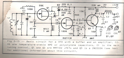
 The VFO circuit comes largely from W1FB's Design Notebook page 36.  I followed most of the conventional tribal wisdom on VFOs:  NP0 caps, often many of them in parallel.  Air core coil (in my case wound on a cardboard coat hanger tube). 


For C1 I used a big variable cap (with anti-backlash gears) that Pete N6QW advised me to buy on e-bay. Thanks Pete.   L1 is on the cardboard tube.  I only built the oscillator and the buffer -- I did not need the Q3 amplifier.  (The water stain in the upper left is the result of a heavy rain in the Azores around 2002 -- water came pouting into the shack.)  

I think the VFO is more stable than the Ceramic Resonator circuit. But I want to go back and give the ceramic resonator circuit another chance...  Miguel PY2OHH has some really interesting ceramic resonator circuits on his site. Scroll down for the English translation: https://www.qsl.net/py2ohh/trx/vxo40e80/vxo40e80.htm

Dean KK4DAS commented that VFO construction is as much an art as a science.  I agree -- there is a lot of cut and try, a lot of fitting the components you have on hand into the device you want to end up with.  You have move both the frequency of the VFO AND the tuning range of the VFO.  Mechanics (in the form of reduction drives) is often involved.  And, of course you have to apply lots of tribal knowledge to get the thing stable. You could, of course, avoid all of this by using an Si5351, but I think that moves you away from the physics of the device, and is just less satisfying. 

So,  JOVO!  LC JOVO!  The Joy of VARIABLE Oscillation!   

Monday, October 25, 2021

Putting a Ceramic Filter in the "Mate for the Mighty Midget" Receiver


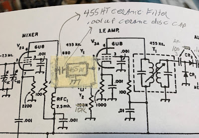
It is really simple.  I had one of the +/- 3kHz (6 kHz wide) 455HT filters on hand.  The spec sheets call for 2000 ohms at both ends, but looking at the schematic it appeared that I already had high impedance on both sides of the filter.  I put a .001 uF cap on the input side to keep the DC voltage off the filter (see above and below). This capacitor allows us to avoid the dreaded problem of electro-migration that is so nicely described by SV8YM here: 


Tasos also provides a good description of the innards of those little black boxes that contain ceramic filters. 

Once you get the filter in your receiver, you have to carefully place the BFO signal in relation to the filter passband.  I have trouble properly sweeping 455 kHz filters -- my HP8640B will not go that low.  Nor will my Antuino (I need to modify the code -- someone help me please).  I know the NanoVNA will do the job, but I just couldn't seem to get it to work.  So I went "old-school" and manually swept the filter using my FeelTech sig gen and my Rigol scope.  This gave me a rough idea of where the passband was.  I put the BFO on the low end of the filter passband, at 451 kHz.

   
With this filter the MMM RX has become a real asset.   The 6 kHz bandwidth allows for nice reception of both SSB signals and AM sigs.   I may try to use one of the +/- 2 kHz filters  (4 KHz wide), but so far I have not been able to find a source for this part. 

Saturday, July 11, 2020

Q-31 Receiver Filter Fix with the NanoVNA


The picture above shows my problem. As predicted by the Murata data sheet and as warned by R.A. Penfold, that nice 455 kc ceramic filter has a significant response at around 640 kc.   This caused me to hear Brother Stair twice as often as I should have.  Clearly a spur exorcism was called for. 


Click on the picture for a better image.  As noted last time, my first idea was to build a series 640 kc trap LC circuit and put it ahead of the ceramic filter.  But I had trouble getting the desired high Q.  So I then thought about putting a wider 455 kc filter ahead of my 12 kc filter.  I would, of course, need one that did NOT have the 640 kc spur.  I found a 455B filter in my junk box.  I used the NanoVNA to look at its response.  No spur at 640 kc!  Yea!  


Next I put the two filters together, 455B first, then the 12 kc filter.  Success!  You can see on the NanoVNA that there is no spur at 640 kc. 

With close to the desired termination impedances, the passband at 455 kc looked pretty good.  I just put 1500 ohm resistors in series at the input and output of the dual filter combo. 

It worked.  Spur exorcised!  I no longer hear each SW broadcast stations at two spots on my dial.  

Friday, November 1, 2019

Direct Conversion (videos)


Here are a couple of videos from 2017 (never posted before).  I built a little 40 meter Direct Conversion receiver for my nephew John Henry.   

Whenever we work on circuitry like this, we should be be grateful for Wes Hayward W7ZOI who, in a 1968 QST article, reminded us of this important but until-then forgotten technique. 

More information on this project appears in these links: 

https://soldersmoke.blogspot.com/2017/10/a-direct-conversion-iphone.html

https://soldersmoke.blogspot.com/2017/11/iphone-direct-conversion-receiver-with.html


Sunday, December 17, 2017

Building the Ceramic Direct Conversion Receiver Part 2 -- Building the VFO -- Our Goal is JOVO!

DC RX VFO and Buffer

I'll put the full schematic at the bottom of each of the posts so that you can easily refer to the big picture. Above you see the schematic of the VFO circuit. 

OK, here we go. Let's build the oscillator.  Our goal is JOVO -- the Joy Of Variable Oscillations. 

At this point you should have a big-enough copper clad board, and you should have given at least some thought to what kind of enclosure you are going to put the board in when you are done.  It pays to think ahead at least a bit, but don't get so carried away with planning that you never get around to building. 

You should plan the allocation of the space on the board.  Think about where you are going to place each stage.  You can mark out the spaces with a pencil or a Sharpie marker.  You might want to look at my board for ideas:     


In the picture above you can see the four stages.   On the left side of the copper-clad board you can see the Front end: the input filter and the RF amplifier (transistor near the top).  Moving toward the center you can see the mixer stage (around the circular 1k trimmer potentiometer).  Below the mixer (near the big round hole in the Bud Chassis) is the Variable Ceramic Oscillator stage and its buffer amplifier. The right 1/3 of the board is taken up by the audio amplifiers.  Note the use of Manhattan pads throughout.    Click on the picture for a closer look. 


Once you know where you will put the VFO, eyeball the schematic and think about where you will need Manhattan pads.  I often start by thinking of three rectangular pads for each transistor, one for each lead.  You can see that there are a lot of parts hanging off each of the terminals.  I sometimes put a long strip across the top or the middle of the board to carry the DC voltage.  

Since this is an oscillator, you don't have to worry too much about keeping the outputs away from the inputs.  You want this one to take of on you. 

For the feedback capacitors (C16 and C17) and the output capacitor (C19)  , get some ceramic disc NPO caps.  I put a 180 pf cap at C17 only becasue I didn't have a second 150 pf cap in the junkbox.  Either value will probably work. 

You will need a ceramic resonator.  I recommend this one from Mouser.  Again, buy a bunch.  They are cheap: https://www.mouser.com/productdetail/520-zta7.3728mt

You can, to start,  build this circuit WITHOUT the two components that allow you to vary the frequency: without L4 and C5.  Just run the left end of the ceramic resonator to ground. See below.  

Connect a 9V battery to the top of C24.  Without L4 and C5 (with one end of the resonator to ground)  you should be oscillating at around 7.168 MHz (the capacitors in the oscillator circuit are pulling the frequency down from 7.37 MHz).

You need some way to find out if it is oscillating.  If you have an oscilloscope, great.  Put the probe at the output and take a look.  But perhaps a simpler and more satisfying way to do this test is with a radio receiver.  Tune the receiver around 7.168 MHz.  You do not need to connect your receiver to the oscillator.  You should be able to hear it.  If you do, congratulations.  If not, check your work.  Be patient.  This is not plug and play radio! 

Once you get the thing oscillating, it is time to make it variable.  Here is an opportunity for variety and experimentation.  Here are some of the options you have: 


Here is what I found.   The frequency stability of these circuits vary.  But all of them are stable enough.  They might drift a bit so that you have to retune the dial every few minutes.  If that realy bothers you you can upgrade to the air core coil with air variable cap arrangement.  

When I put just a variable capacitor that goes from 17 pf to 159 pf between the ceraamic resonator and ground, I was able to tune the oscillator from 7.220 MHz to 7.420 MHz. 

If I put a fixed 8.18 uH coil between the ceramic resonator to ground that moved the frequency to 7.010 MHz.  You could use a toridal core coil for this, but I had best results with an air core coil.  By putting the 17-159 pf variable cap between the coil and ground (similar to the arrangement shown above) I could tune from 7.010 MHz up to 7.367 MHz. 

You could also replace the variable capacitor with a voltage variable capacitnce diode (aka a varactor or a varicap diode).    I had good results with an MV2301.   

You could try using a cheap little polyvaricon capacitor for C5, but my best results came with an air variable. Walter KA4KXX points out that nice variable capacitors are available here: 
https://www.amplifiedparts.com/products/capacitor-365pf-variable  If you can, get one with a reduction drive to slow the rate of tuning as you turn the shaft.  If you can't get one of these, try to get find a reduction drive to slow down the tuning. 

I ended up using a 3 uH air core coil with a variable cap of around 365 pf this allows me to tune from 7.115 MHz to 7.300 MHz (all of the phone portion of the band) with very good stability -- Juliano Criteria levels of Stability.  

One more idea:   As you build this stage, or right after you finish it, go ahead and build a dulicate circuit, perhaps without the variation components.  Why?  Well that second oscillator might be useful when it comes time to peak and tweak the front end input filter of your receiver.  And that second oscillator can become the start of a second version of this project. 

We talked about this project in SolderSmoke Podcasts #199 #200 and #201

Now I'm going to the beach.  I hope the holiday season bring you all joy -- especially the Joy of Variable Oscillations. Send us reports on your progress, your joy, or your tales of woe. 
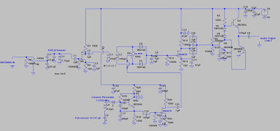
The Big Picture

Sunday, December 3, 2017

Discrete Ceramic 40 Meter Direct Conversion Receiver in Action (Video) -- BUILD THIS THING!


I've been holding off on making this video until I improved the stability.  N6QW is vigilent!  I only did this video after certifying that it meets the Juliano Stability Criteria.  I had to dispense with the polyvaricon and go with an air variable. 

We will be talking about this on the SolderSmoke podcast next weekend.  I hope to put on the blog  a stage-by-stage discussion of how to build this receiver.  

The dial from HI8P and the knob from a SW receiver that Elisa gave me definitely add soul to this new machine.  

JOIN THE RANKS OF THE TRUE HOMEBREW RADO MAKERS!  BUILD A RECEIVER!  BUILD ONE OF THESE!  

Tuesday, November 28, 2017

Videos of iPhone Box DC Receiver


These are just a couple of short videos that I made for my nephew before sending him this receiver. 

As you can hear, deafness is not a problem with this design!   I did make some frequency stability improvements after this video was made -- I think you can hear a bit of drift.  Still, not bad for a very simple circuit using a polyvaricon superglued to the back of a cardboard box.  

I'll post more videos of the second version of this receiver.  There are further improvements in frequency stability.  My goal:  "Juliano Si5351" levels of stable-ness.  

Saturday, November 25, 2017

Polyvaricon Variations -- Polyvaricons Are Not all The Same


When I built the first prototype of the iPhone DC receiver, I just reached into my junk box and used a polyvaricon capacitor for the main tuning control. It was marked PL 051.  I was really pleasantly suprised at the stability of the Variable Ceramic Oscillator circuit.  I could tune the entire 40 meter band with complete stability -- Juliano levels of stability. 

By the time I put the second version into its box (see above), I used a different polyvaricon (the one pictured below).  It worked, but with this part the receiver drifted noticeably.  So this morning I pulled it out and put in a second PL 051 Polyvaricon.  Viola!  Eccolo!  Success.  Drift eliminated.  Rock stable.    

Has anyone else noticed variations like this in the stabilty of polyvaricons?  

The dial in this version is an Archer device that has been kicking around in my junkbox for more than 20  years.  I think it was given to me by my old friend Pericles HI8P -- this adds a tremendous amount of soul to this new machine).   The box is an old Bud aluminum chassis.  Man, this thing sounds great.  I will try to post a video soon. 


Thursday, August 24, 2017

The Return of Pete's Simple-ceiver Plus (and a possible analog option)


Winter is approaching ladies and gentlemen, and it is time to think about radio projects.   Bob N7SUR suggested a direct conversion receiver project.  I think this is a great idea.   As a kid, I had fallen victim to the idea that building receivers was "too hard" for radio amateurs. Not true!  DC receivers to the rescue!  Carry on with the DC revolution first launched by Wes W7ZOI in 1968.

Pete N6QW is providing guidance and tribal knowledge via his blog.  For those of you who want to join the ranks of those who have defied the conventional wisdom and have broken through the "receivers are too hard" barrier.  I say build yourself a DC receiver.  Build it from scratch.  Many of you already got your feet wet in homebrewing with the Michigan Mighty Mite project.  Now it is time to jump into a DC receiver project.  

You folks already know what kind of VFO Pete will prefer:  It will be an Si5351.  That's fine.   But I will try to keep the banner of discrete component analog ludite-ism flying high.  This morning I ordered a batch of 7.37 MHz ceramic resonators.  I hope to pull them down into a significant portion of the 40 meter phone band.  If this works, I will share the batch with anyone who wants to joining my Analog Army (remember the CBLA?).   Note (above) that Pete has magnanimously left open the possibility of using a non-digital VFO. What a guy!    

Check out Pete's project here: 

http://n6qw.blogspot.com/2017/08/a-new-line-of-transceivers-difx_19.html
Designer: Douglas Bowman | Dimodifikasi oleh Abdul Munir Original Posting Rounders 3 Column