Podcasting since 2005! Listen to Latest SolderSmoke

Showing posts with label Toroids. Show all posts

Saturday, March 25, 2023

Update on the High-School Direct Conversion Receiver Project: Board #4 Completed

One of the receivers. (l to r) AF, PTO, Mixer, BP filter

The students continue to make great progress on their direct conversion receivers.  Yesterday they were enthusiastically sitting down to workbenches, building Manhattan-style circuits, working directly from schematic diagrams.  It was really impressive.  They are building receivers. 

This week we had two sessions of about two hours each. We introduced the final board:  the audio amplifier.  Many of the students began work on this amplifier; others were catching up with work on boards presented earlier. 

The AF amp is their most challenging board:  It used 14 Manhattan pads and about 26 components.  We warned the students that amplifiers often aspire to be oscillators.  We told them to pay attention to layout, and to keep their leads short.  

One of my builds, and a Manhattan board pattern

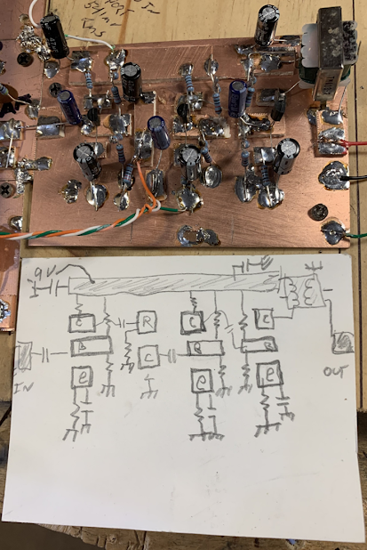
At first, the students just built the first stage on the AF amp board. They tested this, then moved on to build the other two stages.   

By the end of Friday, two groups had completed the build of the AF amplifier board.  

We think there are about 13 receivers in production.  Some are near completion, others will need more work.  

On Thursday of next week those teams that have completed all four boards will put the circuits together and will test the entire system.  They will then add all needed front and back panels and socketry. 

We really want the students to complete as many of these receivers as possible.  Exam season and the end of the school year is approaching, so we have to get this done.  We will remind students that they don't want to that person who ALMOST finished a project!  We will urge them to GET IT DONE!   They can tweak it and mod it later.  This kind of tweaking and modification is part of the homebrew experience. 

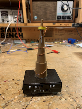
We have been presenting awards to the students who are first to complete each stage:  The winners of the PTO board competition got a copy of SolderSmoke:  Global Adventures in Wireless Electronics.   Those who won the mixer competition got a W1REX Hamfest Buddy transmitter.  Thanks Rex!  And this week we presented an award to the students who were the first to complete their bandpass filter.  You've heard of the Tony, the Emmy and the Grammy?  Well, we presented "The Torry"  (from Toroidal).  The trophy was made from a toroidal winding tool made in Alaska by KL7FLR.  I explained to the students who had made it.  Thanks Paul! 

"The Torry"

Thursday, August 11, 2022

What Coil for the Polyakov Input Circuit? How to calculate a coil value for resonance.


So,  what is the value for L1 and L2?   What coil should I use?  
Michael AG5VG had that question.  And so did I when I built this receiver.  See below for the process I used in answering this question. 

On Tuesday, August 9, 2022 at 10:53:32 PM EDT, Michael S  wrote:

Good Evening Bill,

My name is Michael and I really enjoy your podcast with Pete. I have also spoken with him in regards to the design of a 20M bandpass filter I made for a homebrew rig.  I am currently in the process of making a 20 meter DSB - SC type. Thank you for all the information that you speak and teach about during your podcast. I also enjoy the humor. It's great.

The Polyakov is a simple DC receiver and it amazes me and how the sound quality is. My question is, what is the turns on the toroid for the antenna primary side and the radio secondary and how did you figure out the turns because looking at the schematic it doesn't give that information that I can see. Also how you resonated it with the variable capacitor that looks like a 365pf air variable. 

Thank you for your time and keep up the great work on the podcast and the content on YouTube.

73s,
Michael
AG5VG

My response: 

Good questions Michael.   When I saw the SPRAT article I too was struck by the fact that it didn't give a value for the coil.  But DK2RS did have a large value variable capacitor... And he was billing this as a dual-band (80-40) rig.  So I figured he wanted that LC circuit to resonate as low as 3.5 MHZ and as high as 7.3 MHZ.  So, with a variable cap that goes up to 350 pf, what value L should I use?   I started by calculating the resonant frequency of the frequency mid-way point: 5.1 MHz.   I figured the variable cap should be around 162 pf at the mid-way point.  At this point I went to the on-line resonant frequency calculator: https://www.1728.org/resfreq.htm (a REALLY useful site!).   This site revealed I needed a coil of about 6 uH.  This put me in the ballpark.   But then -- with the site -- I tested it with the values of the variable cap I had on hand.  Mine was 23pf to 372 pf.  (you really need an LC meter to do this kind of thing). 

Again at the resonant freq calculation site:  23 pf and 6uH = 13.5 MHz           372 pf and 6 uH = 3.3688 MHz

This would have been OK, but I wanted to move the frequency range down a bit, so I tried. 6.5 uH 

23 pf and 6.5 uH = 13 MHz                 372 and 6.5uH = 3.23 MHz

Now, how many turns?  First look at the overall coil -- don't worry about taps at this point.    I use the Toroid Turns Calculator: http://toroids.info/

 Start by asking yourself "What core do I have on-hand?    Let's say you have a T-50-2 (red/clear).   The calculator shows you need about 36 turns.  Do-able, but physically kind of tight.  

I found a big core in my junk box.  A T-106-2.  The calculator showed I'd need about 22 turns on this core. It was much easier to get these turns on the larger core.  

You have to measure the core after you wind it to make sure you are at the desired inductance.   One side of the main coil went to ground, the other side to the top of the variable cap. 

 Now for the taps and secondaries:  The schematic shows a tap.  This is usually about 1/4 of the number of turns up from ground.   I picked about 5 turns, and wound a little tap in there at that point -- that tap went to the antenna.  You also have a secondary coil --no value is given, but based on experience I guessed around 5 turns -- I wound these turns on top of the primary one lead went to ground, the other went to the diodes and the switch. 

 The last thing to do is to see if the circuit resonates on both bands that you want to receive.  You can do this with a signal generator, or with the band noise:  Hook up an 80 meter antenna.  Put the cap closer to its max value and tune the cap -- can you hear band noise?  Or can you hear (or see on a 'scope) a signal at 3.5 MHz?   You should be able to peak it with the main cap.  Try to do the same thing on 40 meters -- here the variable cap should be closer to minimum capacity. 

 That's it.  That's how I did it.   You can do it too!   Good luck with the Polyakov.  

 One hint:  Building the VFO is the hard part.  You can get started by using a signal generator in place of the VFO.  Just make sure you have the level right -- around 620 mV input.  

 Good luck -- Let us know if you have trouble. And please let us know how the project goes.   

 73    Bill    N2CQR  

20 meter rig built by AG5VG

Tuesday, August 24, 2021

Mythbuster Video #17 Boxing it Up, Tuning Filters, Tapping a Heat Sink, QRO Dreams....


I made a cabinet out of scrap packing material. I show how I tune LC filters by squeezing the turns on toroidal inductors. I tap a heatsink and think about more power for the Mythbuster.

Monday, April 10, 2017

Very Useful Toroid Info Web Site

This site provides the kind of info we need when working with toroids.  It even tells you the length of wire to cut. It links to the W8DIZ "Toroid King" website, but I can't really tell if this site is the work of DIZ himself.   In any case, very useful.  We award this site our coveted rating of "Five Soldering Irons."


Designer: Douglas Bowman | Dimodifikasi oleh Abdul Munir Original Posting Rounders 3 Column