Podcasting since 2005! Listen to Latest SolderSmoke

Showing posts with label Hayward--Wes. Show all posts

Wednesday, January 31, 2024

My Manhattan-style Termination Insensitive Amplifier Production Line


You gotta love the name, right?  It sounds like some sort of psychological condition.  Perhaps someone who just doesn't care  if his girlfriend breaks up with him, or is indifferent to getting fired.   

But no, we know that that's not what it means. 

I recently had to make three sets of TIA amps for my new 15-10 rig.  First, I decided not to use the boards provided by Todd of Mostly DIY RF.  You can see one of these boards above the tin shears in the picture above.  Note how compact it is.  Even though you would need two of these (one for receive, one for transmit) to get what you need for a bilateral rig like the BITX,  using these boards (as I did on my 17-12 rig) saves you a lot of space.   But this time I wanted to build a rig that is TOTALLY DIY RF.  So out came the tin shears and the super glue. 

First I decided on the Manhattan pad placement.  I used a pattern that had worked on previous rigs. Pete is right -- I use a lot of TIAs (but no, I have no tattoo of the circuit anywhere on my anatomy!).  I scaled it down a bit, thinking that I could come a bit closer to Todd's compactness.  

Knowing that I would need three sets,  I first made three boards.   Then it was just a matter of soldering in the components:  I did resistors, then capacitors, then, finally, the transistors.   In this way I was able to put together the three dual TIA amps in a couple of morning build sessions.  It was kind of tight and I had to be careful to avoid wiring errors or unintentional shorts.   But it worked. 

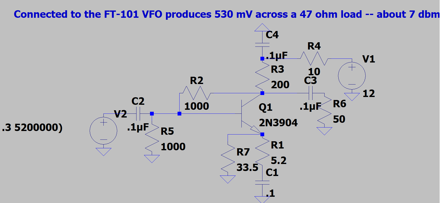
I like the TIA circuit.  It lets me select the gain of a stage by simply using two resistor values from W7ZOI and K3NHI's chart.  And with this circuit I know that it will look like 50 ohms both ways.  This is really important on bilateral rigs like this.  

I don't think there is anything wrong with using BITX-like bilateral circuits or TIAs or LC VFOs.  This is all for fun right?  I just like using these circuits.  

My friend Pete is right in pointing out that the bilateral concept did not originate with the BITX -- it has been around for a long time, going back at least as far as the Cosmophone.  But I think Farhan's BITX definitely moved it into the solid-state homebrew mainstream.   Three cheers for Farhan for doing that.  

Tuesday, September 26, 2023

F6CRP's FB Homebrew Receiver


I like F6CRP's homebrew receiver.  I like the way he presents it (block by block) and I like the inclusion of the W7ZOI IF board. The JF3HZB VFO is quite cool (even though it is digital),   We have posted about this VFO several times: 

Denis has a very nice station and workbench: https://www.qrz.com/db/F6CRP

He also has some very nice videos on his YouTube channel: 

Thanks Denis! 

Sunday, May 28, 2023

Jerry KI4IO (Wizard of Warrenton) Describes His ALL ANALOG Phasing Transceiver -- Bob Crane FDIM interview #3 (audio)

Wow, this one really resonated with me.  Jerry had me won over when, early in the interview, he described his decision to dispense with the Si5351/Arduino combo:  "I said the hell with this digital stuff!"  I hear you Jerry.  I feel your pain OM.  

Jerry then goes on to describe a rig with bits of circuitry from some legendary sources:  The Ugly Weekender transmitter.  SSDRA and EMRFD.  W7ZOI's 1968 Direct Conversion receiver.  

Jerry discusses the "presence" of the direct conversion receiver.  And he decries the pernicious effects of AGC.  (Indeed, real hams MANUALLY control the gain.) 

The Wizard of Warrenton then shares some important tribal wisdom:  After building that new piece of gear, leave it on the bench for a couple of weeks.  Beware of "radio infatuation" (what a great term -- we will have to include this in the lexicon).    Jerry points out that while at first, the new rig will seem just perfect, with time time the need for improvements and modifications will become apparent. 

Jerry also has connections to India and Nepal (where he helped Father Moran).  See: https://www.qrz.com/db/KI4IO

Here is W8SX's interview with Jerry: 

http://soldersmoke.com/KI4IO23.mp3

Thanks Jerry!  Thanks Bob! 

Wednesday, April 26, 2023

Retro QRP Rigs of the 1960's, 70's, and 80's -- Video by Mike WU2D


It is time to put aside (again!) all of the heated ideological arguments about the power level that defines "low power."  Just sit back and enjoy this wonderful trip down QRP memory lane. 

Mike's description of the simple, single-transistor QRP transmitter was really nice.   I recently made something similar: https://soldersmoke.blogspot.com/2023/02/first-qso-with-high-school-receiver-100.html  And Mike does a nice plug for our beloved Michigan Mighty Mite.  Go CBLA! 

The modular idea:  words to live by my friends. 

40673!  TT2!  And G3RJV's PW Severn - indeed, bow your heads!

Wow, the Ten Tec Power Mite (or Might!) -- I still want one.  Same for the Argonaut -- what a great name (sounds like a "magic carpet), and with SSB to boot!  I want to join the Argonaut cult! 

I have both the HW-7 and HW-8 (the HW-8 is heading to the Dominican Republic).  This video makes me want to fire up the HW-7.  Maybe on 40.  

My 40 meter homebrew rig (Digi-Tia) has in it the filter from that old Yaesu FT-7 rig.  The filter was given to me by Steve "Snort Rosin" Smith.  https://soldersmoke.blogspot.com/2015/05/bitx-digi-tia-build-update-2-installing.html  


Thanks to Mike for including me in the credit roll at the end.  What a great group of people -- it is a real honor to be listed with those folks. 

Monday, April 3, 2023

Technology and Methods from Wes Hayward W7ZOI

Great stuff.  Lots of wonderful articles filled with wisdom to ponder. 

 http://w7zoi.net/oldtech/ponder.html

Thanks to Tony G4WIF for spotting this gem and alerting us.  And thanks to Wes for all of this.  


Friday, February 10, 2023

SolderSmoke Podcast #243 -- HI7/N2CQR, uBITX mods for 10 meters, High-School Direct Conversion Receiver Project Launched (Success!) Mailbag

 
DC RX and one of the PTO boards we built as demos last night. 

February 10, 2023


SolderSmoke Podcast #224 is available. 


http://soldersmoke.com/soldersmoke243.mp3


Video here: (32) SolderSmoke Podcast 243 (video) Hi7/N2CQR, uBITX, Success with High School Receiver Project - YouTube


Pete N6QW had technical difficulties this morning.  He insisted that the show must go on.  Pete will be back for the next episode. 


Travelogue: 

Bill in the Dominican Republic for all of January.  

HI7/N2CQR  Eastern tip of the island. uBITX and dipoles. 

20, 17, 10.  CW and SSB.  SSB was tough and I had reports of RF getting into the signal.

Went to CW. 

Worked VWS Mike KA4CDN, and Walter KA4KXX on 20CW.

Finally moved up to 10 CW.  Lots of contacts. Even though uBITX very QRP on ten.

I am modifying the uBITX now.  

Copper tape shielding to keep RF out.

 Low power out not the fault of the IRF-510s.  The problem is the 2N3904s.

Will replace with 2N2222 in To-18 cans.

Dean KK4DAS putting KD8CEC software into Arduino.  I gave up.

Who sent me this orphan uBITX?

SolderSmoke Shack South in final phase of construction.


SHAMELESS COMMERCE DIVISION:

Patreon!

Bezos Shopping!


DC Receiver Project

Local High School radio club. 

Simple:  Like Herring Aid 5 and Wes’s original.

Farhan’s four stages:

BP Filter, Diode Ring, PTO, AF amp. 

Simple Colpitts PTO SURPRISINGLY STABLE.

Simple and easy.  No chips.  No complicated circuits.

Guys have helped test out the design:  Rick N3FJZ, Walter KA4KXX,

Daniel VE5DLD, Stephen VK2BLQ and others. 

First session last night:  We demonstrated build of the PTOs.  

They worked (thank God).


Open Circuits book.

Envelope Detection Controversy

Save the Antenna – Book “Losing the Nobel Prize” K1JT


MAILBAG

--Dean KK4DAS 10 meter DSB!  Tiny SA ULTRA! FB

--John AC2RL on Elmer W3PHL DSB guy

--AC3K reports inventor of Fender Stratocaster guitar was a ham: W6DOE

--AF8E was doing POTA.  I worked him. He said my rig had presence. FB

--Alain F4IET FB DSB rig with mic in Cigar can!

--Daryl N0DP worked him on SSB.  He is homebrewing

--Steve N8NM was in for repairs but is on the mend.

--Rick G6AKG working with sub-harmonic mixers and logic chips

--Paul HS0ZLQ Built DC receiver but looking for something else to build. No DSB!

--Steve AB4I – Coherer, Jagadish Chandra Bose, and Marconi

--Eldon KC5U    Worked VK5QD right after me and mentioned SolderSmoke FB

--Todd K7TFC is building the DC RX.

--Tony G4WIF and Ian G3ROO using automotive relays for antenna switching. FB.

--Dave WA1LBP Great to hear from my fellow Hambassador (Okinawa)

Older post comments:

--Scott VO1DR was also in CF Rockey’s class! (Blog comment)

--Aurora Aug 4, 1972: Twelve people shared memories.  (Blog comment)

--Will WN1SLG Googled novice call and was led to my Novice log.(Blog comment)


Saturday, October 15, 2022

DC Receiver: 100db Gain? Diplexer? VFO in a box?


Here is a progress report on Direct Conversion Receiver developments. Dual Tuned Circuit, Diode Ring with Diplexer, PTO VFO from Farhan's Daylight rig, two stage 49 db BJT AF amp with a transformer. It works very well. I discuss: Shielding of the VFO -- necessary or not? Why brass in the PTO? Do we really need 100db in a receiver, especially with ear buds? Sourcing the AF amplifier's transformer. Using W7EL's diplexer. (I think it has solved my Radio Marti breakthrough problem). Developing a DC RX circuit that can be built by students. I end with a bandsweep of 40 meters that includes CW, FT-8, SSB, and AM

Thursday, October 6, 2022

Adding a Diode Ring to the Direct Conversion Receiver, And How the Diode Ring Works


I take a look back at Wes Hayward's classic DC receiver from the November 1968 QST.
I then try to describe how diode ring mixers work ("the particular go of it") using Alan Wolke's excellent YouTube description as my base.

I present some drawings that I did that use the "crossed diode" diagram as the start.

I also discuss interference from Radio Marti's 250 kW transmitter on 7335 kHz in Greenville NC.

Finally, we listen to the receiver a bit.

Alan Wolke's Diagram

Wes Hayward's 1968 DC Receiver

Thursday, September 29, 2022

A Bout of Direct Conversion-ism in Northern Virginia -- DC Receivers Under Construction


There I was, minding my own business,  when suddenly I was dragged into the construction of Direct Conversion receivers. 

Here is a video about my latest effort.  But I feel the urge for more simplification -- I may go back to the seminal DC receiver designed by Wes W7ZOI and presented in the November 1968 issue of QST.  It is on page 15 here: https://worldradiohistory.com/Archive-DX/QST/60s/QST-1968-11.pdf

Sunday, September 11, 2022

An Especially Good (Old) SolderSmoke Podcast


February 22, 2008    
-- We were in Rome.  
-- I read a 1931 QST ad sent to me by my fellow "Hambassador" David Cowhig, WA1LBP; David was in Okinawa when he sent it. 
-- I describe Wes Hayward's comments about Pat Hawker, G3VA. 
-- I talk about getting on the air with my HW-8 (after fixing it!), re-tubing my Drake 2-B, and putting up a 30AWG antenna in Rome. 
-- I describe meeting up with Roman hams (including amplifier manufacturer I0ZY!) and visiting the local radio club.
-- The Science Museum in Florence, Italy. 
-- DSB from Rome with my NE602 rig. 
-- Tony Fishpool and Graham Firth's Test Gear book. 
-- An important corollary to Murphy's Law. 
-- Listening to SolderSmoke from safari, under the Southern Cross in South Africa. 
-- Ron Sparks calls in from Dubai. 

You can put on a playlist of all the SolderSmoke podcasts here: 

Monday, August 22, 2022

Mike Caughran KL7R's Last Podcast

 
Mike KL7R (SK) during a visit to the AL7FS shack.


This was Mike Caughran KL7R's last podcast. He died in a car accident shortly after we made this program. January 13, 2007. Mike's oscillator work. Michigan Mighty Mite. Lasers, diodes, and Einstein. Laser communication experiment. W7ZOI-KL7R QSO on SKN.M0HBR's feedback amps.The new comet. Saturn, Jupiter and calculation of c. 17 meter QSOs. New SPRAT CD. MAILBAG: China enigma, VE4KEH, M0DAD, GU0SUP, M1CNK, K4AHU, KD4EDM, KG9DK, AA6KI, VA7AT ON5EX
---------------------
Mike's Obituary from the February 2007 ARRL Letter:

Mike Caughran, KL7R, SK: Well-known low-power (QRP) and homebrewing
enthusiast Michael S. "Mike" Caughran, KL7R, of Juneau, Alaska, died January
22 of injuries suffered in an automobile accident in Hawaii. He was 51.
Caughran may be best known as one-half of the team -- with Bill Meara,
N2CQR/M0HBR -- that created and produced the weekly SolderSmoke podcast
<http://www.soldersmoke.com/>. "I think people were drawn in by Mike's
friendly voice and manner," Meara commented on a memorial page for KL7R
<https://kiwi.state.ak.us/display/mc/Home>. A member of ARRL and the Juneau
Amateur Radio Club, Caughran also wrote articles for the Michigan QRP Club's
T5W newsletter and he was an active ham radio contester. "Mike was one of
those people who you instantly like because of his honest, straightforward
and humble way of talking and expressing ideas," said Mike Hall, WB8ICN, who
edits T5W. "His co-hosting of SolderSmoke provided me hours and hours of
enjoyment." Caughran was an IT professional with the State of Alaska.
Survivors include his wife and son.

Saturday, May 28, 2022

"Experimental Methods in RF Design" LADPAC Software Available FREE!


We've frequently said that is pays to check the W7ZOI web site.  Tony G4WIF did just that and pointed us in that direction, noting that the LADPAC "Ladder Package" software is now available for download from that site. 

Homebrewers will really want to have that package on their computers.  There are all kinds of useful programs in that package:  software for designing crystal filters and feedback amplifiers, a program that allows you to think systematically about receiver gain distribution and dynamic range, and many other useful things.  

You can get the program here: 

http://w7zoi.net/emerrata.html

Also on Wes's site is this May 22, 2022 picture of Farhan VU2ESE with EMRFD co-author Bob Larkin, W7PUA. 

Thanks Wes! 

Tuesday, March 22, 2022

Receiver Dynamics -- How Good is my Receiver?


OK , so I've finished building my new 17-12 Dual Band SSB Transceiver.  I am now testing it out on both bands.   A big question I have is this: how good is my receiver?   Did I get the gain distribution right?   Is it generating too much noise?   Are any of the stages too vulnerable to distortion in the presence of large signals?  

These kinds of questions are at the heart of receiver design.  Many of us have for years just thrown together amplifiers oscillators and mixers, and have been pleased if we could copy signals on the ham bands.  But could we have been doing it better?   

This is a very complicated issue, and unfortunately much of the literature is plagued by jargon and unnecessary complexity.  Rarely do we find something that goes from the general to the specific and explains what it is we are trying to achieve:   We want the receiver to be sensitive, but we don't want it to be so sensitive that it distorts with strong signals.  It will make some noise, but we don't want the receiver's internal noise to be stronger than the noise coming in from the antenna.  The "front end" stages are very important because any flaws there will be amplified by the follow-on stages and will "cascade" down through the receiver.  Bandwidth is very important. 

This morning I found (again!) a document that defines terms in a very clear way.  Be sure to check out the footnotes mentioning Dave Newkirk and Wes Hayward!  FB!  Here it is:

https://www.nsa.gov/portals/75/documents/news-features/declassified-documents/cryptologic-quarterly/Receiver_Dynamics.pdf

Tuesday, January 4, 2022

Exorcism Completed! Getting Rid of the Spur in my 17 meter SSB Transmitter using a TinySA (video)

To re-cap:  The problem became evident when trying to "net" or "spot" my transmitter onto my receive frequency.  Around 18.116 MHz, I could hear at least two tones in the receiver as I moved the transmitter frequency.  I needed to get rid of the extra tone. 

First, thanks to all who sent in suggestions.  They came in literally from around the world, and this is a demonstration of the IBEW in action.  I used or at least tried all of them.  They were all good ideas. 

Following Vasily Ivananeko's pseudonymous suggestion I rebuilt the carrier oscillator (apologies to G3YCC).  I used the carrier oscillator/buffer circuit from Farhan's BITX20.   

Henk PA0EME said I should look at the signal level at the input ports of the NE602 mixer.  Henk was right --- the VXO input was far too high.  I lowered it, but the problem persisted. 

At first, I thought that the spur in question was so small that it would not show up on the air.  I could not see it in the TX output using my TinySA spectrum analyzer.  That was good news and bad news:  Good that it was not showing up on the air, bad that I could not see it in the TinySA and use that image in the exorcism. 

At first I thought that the spur was being caused by the 10th harmonic of the carrier oscillator and the third harmonic of the VXO.  This seemed to fit.  So, following VK3YE's sage advice, I built a little 69 MHz series LC trap (using a coil sent by AA1TJ, on a board CNC'd by Pete N6QW).  That trap succeeded spectacularly in crushing the 10 harmonic.  Look at these before and after shots on the TinySA: 

Before Trap

After Trap

Spectacular right? But guess what?  The problem was still there.  

I scrutinized the situation once more. I realized that the spur would be more visible if I put the TinySA on the input of the transmitter's PA (a JBOT amp designed by Farhan) as opposed to putting it on the output.  Watching the spur and the needed signal move in the TinySA as I tuned the VXO, I realized that they were moving in opposite directions.  This indicated that the spur was the result of a carrier oscillator harmonic MINUS a VXO-generated frequency (as the VXO frequency increased, the spur frequency decreased).  Looking at my EXCEL spread sheet, I could see it:  8th harmonic of the carrier oscillator MINUS the main output of the VXO. 

To confirm this, I plugged the values into W7ZOI's Spurtune program.  Yes, the spur popped up and  moved as predicted.  

For further confirmation I shut down the carrier oscillator by pulling the crystal from the socket, and then just clipped in a 5.176 MHz signal from my HP-8640B signal generator (thanks KB3SII and W2DAB). Boom!  On the TinySA, the spur disappeared.  Now I at least knew what the problem was:  a harmonic from the carrier oscillator.  

Following good troubleshooting practice, I turned off the gear and went to bed.  When I woke up, an idea came to me:  Before launching into a lot of filtering and shielding, just try running the carrier oscillator at a lower voltage, seeing if doing so might reduce the harmonic output.   I disconnected the carrier oscillator board from the main supply and clipped in a variable voltage bench supply.   Watching the signal on my TinySA, I watched as the spur completely disappeared as I reduced the voltage from around 13V to 10V  (see video above).  The main signal frequency level did not change much.  I tested this by listening for the hated extra tones.  They were gone.  Exorcised.  

Key lessons: 

-- Spur problems are difficult to troubleshoot.  Armstrong's superhet architecture is, of course, great, but this is definitely one of the pitfalls.  Single conversion makes life easier.  IF selection is very important. Choose wisely! 

-- When looking at the TinySA as you tune the rig, pay attention to which way the spur is moving.  This provides an important clue regarding the combination of harmonic you are dealing with. 

-- The TinySA is a very useful tool.  It seems like it is easier to use than the NanoVNA (which is also a fantastic tool). 

-- It can be fun and rewarding to re-visit old projects.  In the years between original construction and the re-look, new test gear has become available, and the skill and experience of the builder has improved.  So problems that once seemed insurmountable become fix-able. 

-- Thinking through a problem and thinking about possible solutions is very important.  It pays to step away from the bench to think and rest.  Rome wasn't built in a day. Here's a rough block diagram that I drew up (noodled!) while trying to figure out this problem: 

Tuesday, December 28, 2021

How to Fix the Spur Problem in my 17 Meter SSB Transmitter?


I built the transmitter almost 20 years ago.  It is in the larger box, which originally housed a Heathkit DX-40.  There is a lot of soul in that old machine.  Details on this construction project are here: https://soldersmoke.blogspot.com/2021/12/junk-box-sideband-from-azores-2004-qst.html  (The smaller box is a Barebones Superhet receiver set up for 17 meters.) 

In the 2004 QST article I discuss a problem I had with "spotting" or "netting."  This is something of a lost art, something that you had to do back in the pre-transceiver days, when running a separate transmitter and receiver.  This was how you got the transmitter on the receiver's frequency.  Essentially you would turn on the carrier oscillator and the VFO and let a little signal get out, enough to allow you to tune the VFO until you heard zero beat on the receiver.  My problem was that around one particular frequency, I would hear several zero-beats.  This made netting the receiver and the transmitter hard to do.  

Important note:  This is really just a problem with the "netting" or "spotting" procedure -- the problematic spur does not show up in any significant way in the output of the transmitter.  I can't see it on my TinySA.  But it is strong enough to be heard in the unmuted receiver sitting right next to the transmitter. And that creates the netting problem. 

In the QST article, I said that I noticed that the problem seemed to be centered around 18.116 MHz.  As I approached this frequency, the tones -- desired and unwanted -- seemed to converge. That was an important clue.  In the article I said I thought that I could eliminate the problem with just one trimmer cap to ground in the carrier oscillator, but looking back I don't think that this really fixed the problem. 

I recently took a fresh look at it.  Exactly which frequencies were causing the unwanted signals that appeared in my receiver? 

I used an Excel Spread sheet to find the culprits. 


The first column shows the carrier oscillator and its harmonics.  The second column shows the VFO when tuned for a signal at 18.11668 MHz (23.2927-5.17602), along with its harmonics.  Check out the 10th harmonic of the carrier oscillator and the third harmonic of the VFO: 69.8781-51.7602 = 18.1179.   Those two harmonics would produce the problem I had been experiencing. 

I turned to one of Wes Hayward's programs for confirmation.  Spurtune08 came in the EMRFD software package. Here is what I saw when I plugged in the above frequencies:    


You can see the little spur off to the left of the main signal.  In the program, as I tune the 23 MHz VFO frequency, the spur moves closer to the main frequency as I approach 18.116 MHz, just as it does in the real rig.   Note that I have only turned on the 10th harmonic of the carrier oscillator and the 3rd harmonic of the VFO.  Spurtune08 is very useful.  Thanks Wes! 

So, what is to be done?   For now, I am just restricting my operations on 17 meters to above 18.120 MHz.  (I worked several DX stations with it on December 27.)  But obviously I need to fix this. This rig needs an exorcism.  I think I only need to get rid of one of the harmonics, and the 10th harmonic of  the carrier oscillator seems easier to kill.  I'm thinking of putting the carrier oscillator in an Altoids box, and then adding some filters to knock down the 10th harmonic. 

Here is the G3YCC schematic that inspired this rig.  I used G3YCC's carrier oscillator and balanced modulator circuits, just using a 5.176 MHz crystal and changing the tank circuit in the collector: 


How would you folks knock down that 10th harmonic? 

Tuesday, November 2, 2021

Farhan's Amazing Knack Story: From a Boyhood SW Receiver to the Design of the sBITX SDR


The presentation starts at about the 4 minute point. 

I think if I were only allowed to watch one YouTube video in the next year, I'd make it this one. 

In this amazing RSGB video, Ashhar Farhan VU2ESE takes us back to his earliest days as a radio amateur.  He tells us about his very early desire to build radios, his early projects, and his personal evolution as a designer and builder,  from a simple DC receiver, to the BITX, the Minima, the uBITX and now the hybrid HDR/SDR sBITX.  

There is a lot of  homebrew wisdom and tribal knowledge in this video. And we learn so many hitherto unknown details about the rigs that have become so important to us:  

-- Farhan had the EMRFD book with him on the famous flight from Sweden to India during which the BITX was designed. 

-- We learn about the origins of the BITX oscillator circuits, and that the VFO and BFO are essentially the same.  

-- I was really pleased that Farhan included a picture of my HB BITX17 rig in his presentation. 

-- Farhan discusses the difficulties he faced in obtaining needed parts in India. 

-- We actually see the nylon washers that Farhan used in the original BITX. 

-- Farhan discusses his early system for measuring coil inductance. 

-- In addition the huge contribution of EMRFD,  Farhan talks about how he was helped by Pat Hawker G3VA's writing, and the ARRL's SSB Handbook. 

-- Farhkan talks about his Tex 465 'scope and his building of a Spectrum Analyzer. 

-- We see his evolution to dual conversion. We see the conceptual birth of the Minima and the birth (thanks Wes!) of the TIA amps.  I didn't know about the HF-1.  Then Farhan designed the uBITX and now the sBITX.  

 -- Farhan talks about his practice of taking the pictures of new rigs with the new rig sitting atop the book that was most important in its design and construction.  FB. 

-- I was really blown away by Farhan's presentation of how the uBITX advertisement was inspired by and in many ways based on the Heathkit ad for an HW-101.  Amazing. 

-- I learned a lot from Farhan's discussion of SDR theory.  I pledge to spend more time with this.  I really like Farhan's hybrid HDR/SDR approach. 

-- But I have a question:  Farhan seems to say that we'd need a big expensive GOOGL computer to do the direct sampling HF SDR.  But doesn't the little RTL-SDR do just that?  Without a GOOGL?  

-- Great to see Wes's AFTIA being used in the sBITX.  

-- Really cool that Farhan has his mind on VHF transverters when designing the sBITX.   I liked use of the TCXO module to free up one of the Si5351 clock outputs.   FB.  And great to include an idea from Hans in this rig. 

Thanks very much to Farhan (who stayed up until 3 am to do this!) and to the RSGB for hosting.

Monday, August 30, 2021

Adding Automatic Gain Control to the Termination Insensitive Amplifier

 
Earlier this month Paul VK3HN had a very interesting blog post about adding Automatic Gain Control to Termination Insensitive Amplifiers (TIAs).  

Termination Insensitivity is especially important in bidirectional rigs.  The shape of the crystal filter bandpass response is very dependent on the impedances presented at both ends of the filter.  In bidirectional rigs you are changing the signal path direction through the filter when you go from transmit to receive.  If the amplifiers at either end of the filter have impedances that vary depending on what is on the input or output of either stage, you will have great difficulty keeping the bandpass identical as you move from transmit to receive.  Termination Insensitive Amplifiers let you do just that -- they stay at one fixed input or output impedance (usually 50 ohms) independent of what is attached to the other end of the amplifier circuit.  This greatly simplifies impedance matching at the ends of the crystal filter. 

When I started building BITX rigs, I asked Farhan about the impedance matching problem.  He advised me to use TIAs on both ends of the filter and pointed me to a great 2009 article by Wes Hayward and Bob Kopski.  Using the information from that article, I built my DIGI-TIA transceiver, and I have used TIAs in almost all of the rigs I have built since that project.   

In his August 2021 blog post, Paul wanted to add Automatic Gain Control to the TIAs. He came up with a way to do this, but we worried that his circuit would have an impact on the impedance of the amplifiers. 

Yesterday, Wes Hayward W7ZOI posted on his web site a TIA circuit that lets us do it all:  Termination Insensitivity with Automatic Gain Control: 


I now find myself tempted to rebuild one of the TIA stages in my Mythbuster transceiver, adding the AGC circuitry from Wes's design. 

Thanks to Paul VK3HN for the blog post on this subject. And thanks to Wes Hayward for the TIA AGC design.  It is a real privilege to have direct input from Wes on questions like this. 

Tuesday, August 3, 2021

AFTIA! The Audio Frequency Termination Insensitive Amplifier from W7ZOI


It really pays to check Wes Hayward's web site.  I looked yesterday and found something that we really need:  A termination insensitive amplifier for audio frequencies -- an AFTIA.  Just last week I was looking at the AF amplifier of my Mythbuster rig, wishing that it had TIA properties.  Now, thanks to Wes, we have a circuit available: http://w7zoi.net/audio-fba.pdf

And let's not forget that it was Wes Hayward W7ZOI and Bob Kopski K3NHI whose 2009 article alerted us to the RF variety of termination insensitive feedback amplifiers. 

Tuesday, July 13, 2021

Mythbuster Video #3 -- Using the VFO from a Yaesu FT-101


FT-101 VFO

I used LTSpice and Wes's FBA program (from LADPAC) to come up with a circuit that would provide the needed gain. I needed to get the 290 mV rms signal (across a 50 0hm load) up to the 500 mV rms signal needed by the ADE1 mixer.  Above is the amplifier that I came up with.  The key here is to adjust R2 and R1 to get the required gain. 
Designer: Douglas Bowman | Dimodifikasi oleh Abdul Munir Original Posting Rounders 3 Column