Just go to http://soldersmoke.com. On that archive page, just click on the blue hyperlinks and your audio player should play that episode.
http://soldersmoke.com
This is probably Jean Shepherd's best program about homebrew ham radio. It is about how we can become obsessed with the problems that arise with equipment that we have built ourselves, and how normal people cannot understand our obsessions.
I posted about this back in 2008, but I was listening to it again today, and quickly realized that it is worth re-posting. Realize that Shepherd's Heising modulation problems happened almost 90 years ago. But the same kind of obsession affect the homebrewers of today.
Note too how Shepherd talks about "Heising" in Heising modulation. Heising has an entire circuit named for him, just like Hartley, Colpitts, and Pierce of oscillator fame. Sometimes, when I tell another ham that my rig is homebrew, I get a kind of snide, snarky, loaded question: "Well, did you DESIGN it yourself?" This seems to be a way for appliance operators to deal with the fact that while they never build anything, someone else out there does melt solder. They seem to think that the fact that you did not design the rig yourself makes your accomplishment less impressive, less threatening. This week I responded to this question with Shepherd's observation -- I told the enquiring ham that my rig is in fact homebrewed, but that I had not invented the Colpitts oscillator, nor the common emitter amplifier, not the diode ring mixer, nor the low-pass filter. But yes, the rig is homebrew, as was Shepherd's Heising modulator.
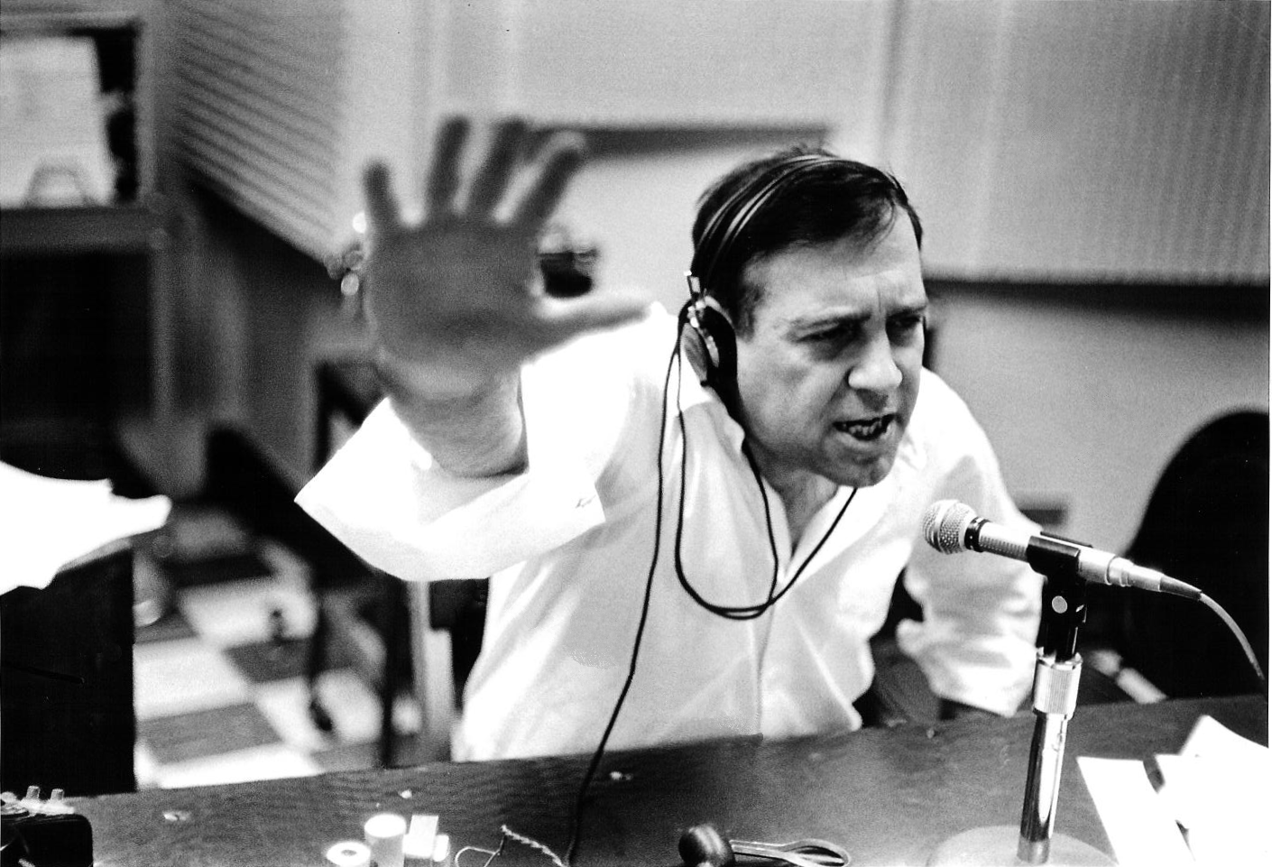
Guys, stop what you are doing. Put down that soldering iron, or that cold Miller High Life ("the champagne of bottled beer") and click on the link below. You will be transported back to 1965 (and 1934!), and will hear master story-teller Jean Shepherd (K2ORS) describing his teenage case of The Knack. He discusses his efforts to build a Heising modulated transmitter for 160 meters. He had trouble getting it working, and became obsessed with the problem, obsessed to the point that a girl he was dating concluded that there was "something wrong with him" and that his mother "should take him to a doctor."
This one is REALLY good. It takes him a few minutes to get to the radio stuff, but it is worth the wait. More to follow. EXCELSIOR! FLICK LIVES!
Joe KA1BWO is a well-known AM operator who moved West to Idaho several years ago. We had a very nice contact on 10 meter AM on January 14, 2024. See the video above.
I was using an old CB rig that I had converted to legitimacy on 10 meters using the mod developed by Jerry K5JC:
Eldon did the mod and we have been trying to make contact. We did so today. It was very cool. I was on my GE rig; Eldon was running a JC Penny! (See video above.) 1054 miles. Thanks Eldon. And thanks Jerry!
See video above. This happened on my second day on 10 meter AM. I was using the little GE CB radio that I had modified for 10 meters. I had lucked out. First bit of luck: the CB that I bought (for parts!) at a hamfest turned out to be just the thing I needed for a quick and easy mod. The GE box had what is called a Hygain board and -- most important -- a PLL02 chip. Second bit of luck: I stumbled across an article by Jerry K5JC on how to put this particular kind of device onto 10 meter AM. Boom, Bob was my uncle, and I got on 10. Then, today, the miracle happened. I heard Benny K5KV and I gave him a call. He asked about my rig. I described the mod to the GE CB. Benny seemed kind of surprised, and for good reason. You see, Jerry K5JC (the guy who created the mod that I was using) had just broken squelch on Benny's rig! Benny told him to get on 10 and soon I as in contact with the guy who had created the mod that I was using. The Radio Gods Have Spoken. Thanks Benny and thanks a Jerry. This was all really cool.
Think of odds of this happening: On my second day on 10 AM, running just 4 watts, I just happened to contact Benny K5KV in Texas who just happened to be in 2 meter range of Jerry K5JC, who just happened at that moment to be breaking squelch on Benny's 2 meter rig. TRGHS.
Here we have a Michigan Mighty Mite being modified for AM in Romania, with input from Hungary, and inspiration from Melbourne, Australia (Peter Parker VK3YE). With a very nice shout-out to SolderSmoke.
I really like Ciprian's emphasis on having fun with the electronics.
Helge is an amazing homebrewer. Check out the shack. Note the R-390 and the Tek 'scope. Watch how Helge designs his rig. Watch him check the 3-D printed coil and the variable caps for resonance. Most of all, watch his happiness when the new transmitter works. I just wish he would have showed us some OM complaining that he was on the "wrong" sideband. FB Helge! Thanks.
Jose CO6EC sent us more information about homebrew rigs built in Cuba. The transmitter above is a thing of beauty. I am really glad that Jose has held on to it. Thanks Jose!
Jose CO6EC today
Jose CO6EC writes:
This is another work from that time: an AM and CW transmitter of about 100W of power, with an on-board modulator. It was taken with some modifications from a Handbook from the 50s. Here goes: it was built with what we had on hand at that time, it still exists, I keep it as a relic of those years.
It used combined Soviet and American tubes in the RF sections: Soviet 6P9 and (2) 6146. The modulator used Soviet 12AX7, 12AUT and (2) 6P7. The 6P9 works as a crystal oscillator, and in case of using an external VFO it works as an amplifier and doubler or tripler to obtain outputs in the 160,80,40,20,15 and 10 Meter bands.
The VFO was also taken from a 1949 Handbook if I remember correctly, but I don't have any literature on that, as you can see in the photo it has 5 5u4c rectifier valves, VR150 voltage stabilizer, 6v6 output, another 6v6 as a separator and a 6 )I(4 (60I94?) Soviet, in the oscillator. The stability they achieved in those years is incredible, I could communicate with stations that were on LSB and if I didn't tell them that I was on AM they didn't notice.
As a receiver I used an old Soviet AM and CW receiver, used by the Aviation HF stations of the 40s, which no longer exists hihihihihi
I'll tell you how I tuned all that good ftuff: First I put the receiver in CW to beat the signal of the stations in SSB. After hearing them clearly, I removed the oscillator of the receiver and connected only the VFO of the Transmitter, and beat the signal with that of the receiver until I heard the other station clearly, then I put the transmitter to work and was ready to communicate.
There were many communications made with that station, even internationally on phone and CW.
Today everything is easier because with transceivers it is not necessary to go through all that work, but it is always good that those who did all this work know how radio was built and made.
73 Jose CO6EC
Obviously the transmitter
The two pictures above must be the VFO. It looks like the VFO in the 1947 ARRL Handbook.
I wonder what handbook this was? Spanish language.
I will be sending you some work of homebrew from the 80's and 90's when practically everything was manufactured by Cuban radio amateurs
The photos are of a Modulated Amplitude TX for the 160 Meter Band, about 25W of which several were made. The final tube was modulated in many cases by a 6DQ6, 2E26 or other similar ones that were very abundant at that time.
This one in particular ismade with valves6BH6 for the VFO, 6CL6 for the amplifier step and 6P23 Soviets in the final part, the modulator was made up of a 12Ax7 microphone preamplifier and a 6BM8 that came out through the cathode to the screen grid of the 6P23, in this way the carrier was controlled by modulation what we calledCarrier Controlas there was no voltage on the grid at the ends there was practically no carrierin the air which gave the impression of transmitting in SSB. hihihihihihi
For those who did not have a communications receiver, a conventional radio was adapted to receive that band, which in many cases was a VEF-206 of Soviet construction, to which an oscillator was adapted to beat the signal and get exactly on frequency. This was very popular here in the late 80's and early 90's.
Thanks Jose. We look forward to learning more about Cuban homebrew. The way in which radio amateurs got on the air with gear that they made themselves using the limited parts available to them is really interesting and admirable. 73 Bill
This article, the pictures, and the comments are all so cool. They really capture the spirit of homebrew. Obviously we still need more information on the Islander and the Jaguey. If you have it, please send it to me and I will disseminate it via this blog.
I've been in touch by e-mail with Jose Campos CO6EC (the guy in the picture above). He sent me this partial schematic of the Islander (we still need the VFO circuit and the RF amplifier) . Thanks Jose!
Views: 2274
Comments: 6
Remembering
By José de Jesús Enríquez Campos (CO6EC)
Next 2019 will be the 30th anniversary of the first convention of radio amateurs in the province of Villa Clara, in Campismo de Ganuza, municipality of Corralillo, on the North coast, about 100 kilometers from Santa Clara, the provincial capital.
This convention was held on a national basis and colleagues from all the country's provinces participated at that time. We did not reach a thousand members throughout the national territory and most of the radio amateurs worked in the 40-meter Band in Amplitude Modulation Then the Lateral Side Band (SSB) was the privilege of a few and the 2 meters was something rare, which did not yet exist in our environment.
At that meeting, a project for a Tube Transceiver was presented, quite simple, with just six vacuum tubes and a BF310 transistor. It was possible to work in HF in Double Sideband, achieving a greater efficiency than the transmission in Modulated Amplitude (AM). This project became known as the Islander.
In only two printed plates, one for the VFO and another for the TX and RX part, which by the way were printed for distribution, in a company in Villa Clara, due to their easy construction and acquisition of the components (almost all of them came out of a Krin-218 TV), a large number of such equipment were manufactured by radio amateurs from all over the country. Like everything made at home, it always comes up with a little problem that later is necessary with tinkering, correcting it.
I remember listening to an old radio amateur from Havana (whose callsign I don't remember) in a pleasant QSO with another colleague, who jokingly said, "... some "Bugs" have now appeared in the band, called Islander, which is worse than the invasion of the Vikings…”, which gives an idea of how many were built at that time, when if you wanted to make radio, you had to manufacture it, something unusual in these times.
As soon as we saw the project we decided to build it, because at that time we had an AM “transmitter” with modulation by “Carrier control” with four tubes, a 12AX7 preamplifier; an ECL82, as a modulator, with cathode output to the final tube Screen grid, a 6DQ6 and a 6BH6 as VFO; and to receive, an old Russian receiver from World War II.
We got involved in the construction and improvements of the project and we managed, with some changes, to improve its performance and quality, because among the modifications to the original, we added:
-A switch, with which you could change the transmission mode to DSB -CW-AM. -A "Pi" Filter at the input of the RX, which considerably improved its quality. -An automatic volume control, because since it did not have AGC (Automatic Gain Control), when someone nearby came on, it would break your speaker. -A filter for the microphone input, which improved the quality of the modulation. -A final power stage, with a 6146B, with 750 V on the board, for about 70 W of output, taking advantage of the 6P15P as Driver. -The chassis was built from scratch using aluminum trays that were sold at the hardware store for “four pesos” each and that were special for making cabinets for these purposes.
After the construction was completed in one afternoon, with Reinaldo Martínez Domínguez (CO6UK), from Manicaragua, the balanced modulator was adjusted, since the good transmission of this type of equipment depends on the relationship between the amount of RF and audio that are mixed At that stage, it took us a long time to adjust, until Reinaldo with his expert ear told me, “leave it there, don't touch it, it's 99% complete”.
There were many international contacts that I was able to make with this very simple equipment, with very good reports, many of them with Europe, the American continent, that was very normal, since the propagation conditions in those years had nothing to do with the today, you could do half the world in AM, with about 100 W.
Many colleagues at that time asked me what equipment I was using. When I told them it was an Islander, they asked me to send them the plans of the improvements made, they were many modified plans, mimeographed.
Perhaps the youngest do not know what that was and the photos taken by colleague Joel (CO6JC) that helped to illustrate the distribution of the components in the chassis, were sent to radio amateurs from the different provinces, in the interest of contributing modestly to migrate from AM to the Double Side Band, today it is a rarity to listen to someone on AM, there are already few who appear in Double Side Band, which shows that we have developed in these almost 30 years, despite the difficulties, which We went from just under a thousand to about 8,000 throughout the country today.
From time to time, a colleague in the 40 meter Band, from another province, has told me that he still keeps the plans and photos that were sent to him at that time, or as "Kike" (CO6GO) that he still has a Islander as a relic.
Ours passed away a long time ago and part of its components went to other projects, thanks to Joel (CO6JC) there is a graphic record of it, and that at that time I had hair, which I have lost in these bustles.
With this brief comment, we only want the new generations to know what radio amateurs were like in those days and the older ones to remember it.
Nothing, to remember is to live again.
Here he left you some images.
(co6ec) Jose de Jesus Enriquez Campos
The first Image was the prototype presented at the Ganuza meeting, the rest of the photos were the ones we built with the improvements, and the photos and plans were sent to many colleagues, the colleagues who went to that meeting will remember, well, they still have to there are many left, because that was almost 30 years ago, greetings CO6EC
(co8zz) Raul Verdecie
Magnificent photographs!!!... They seem to have been taken today with some digital "super camera"!!! Really, from what I can see now, the CO6EC Islander was the perfect example... mine (my first radio and built by me) was also made like this, with the plates that the FRC sold and it was good, but very ugly ...HI... The AGC worked wonderfully as it came, I don't know if Jose's improvements were later! With it I made my first hundred or so entities only in 40 meters / CW (between 7,100 and 7,150) when it was CL8ZZ. I gave it away so that someone would have their license and now I regret not having kept it... I would have liked to show it now to those who regret not having a radio!!!
(co8zz) Raul Verdecie
Ah, I can never forget those headphones!!!... my external hearing aids (read ears) are much smaller today thanks to them, they exerted tons of force on the operators' skulls!!!
(cm6vml) Vidal
Very good article, I hope that one day, with a good teacher, I can build my own team, congratulations Jose, regards Vidal.
(co7wt) Pavel Milanes (CO7WT)
Sure...
My first radio and with which I got my CL7WT license back in the 90's an ISLANDER, like that in capital letters.
I remember that the CL only had a small 40m segment (like now) and that it was full of broadcasts as soon as the afternoon fell, it was an odyssey to speak on the radio... you had to find a "little hole" between the Broadcastings where it wouldn't bother you " a lot" to be able to talk.
I remember that the old CO7OC (he is no longer a radio amateur) and CL7HU (now AC7HU) helped me build it with a board I bought at the radio club. I took almost all the valves from the deceased KRIM 218, then I found a store in Camagüey that sold idle things from the workshops...
Turns out they had such a large inventory of "idle" tubes that they couldn't put it on the counter...they let me through to the warehouse...huge...stack of tubes, if I remember correctly I ended up with Chinese or Japanese tubes that they were more sensitive in the receiver... the driver went from a 6P14P to a more robust 6P9, by the end that was a humble 6P44 it became two 6P7s that were a Russian version of the RCA 607 if I remember correctly... in the end it had like 80W.
It goes without saying that when I said on the radio that there were valves in that place "they flew"....
The VFO was the one from the Jagüey, not the original from the Islander, I never knew about the AGC modifications.
I would like if someone has the plans with the modifications to send them to me, just for nostalgia...
My email pavelmc@gmail.com
(co2jc) Carlos Alberto Santamaría González
Brother, your article is very good, because of the nostalgia and also because it talks about what we radio amateurs like: tinkering. I didn't have an Islander because what I started with in 2000 was a Polosa to which two colleagues helped me adapt it with VFO for 40 and 80 m. But I talked a lot with colleagues who did it with an Islander or a Jagüey and participated in the Rueda del Behique that I started in the 80 m. Others in the Hurricane Wheel that started a little later and were heard well. As you well say, the propagation at that time had nothing to do with what it is now, but it was very good to listen to the colleagues who came out with the equipment they had built. Thank you once again for your article. CO2JC
Recently a fellow ham claimed that "envelope detection" doesn't really exist, and that the standard "rectification and filtering" explanation of how envelope detectors work (going back to Terman and beyond) is wrong. But here is a good demonstration of the envelope detection of an AM signal. It uses an infinite impedance detector built around an FET. As Baltic Lab notes in the video above, the action is essentially the same as what happens with a vacuum tube: The device is biased at cut-off. The negative portion of the ENVELOPE is discarded. The positive portion of the ENVELOPE is passed through the device and filtered. What remains is the audio -- the same audio frequency that modulated the carrier. ENVELOPE DETECTION.
I was thinking about how fortunate we were that this form of detection was possible. Fessenden used what were in effect diode detectors to envelope detect very early transmissions of radiotelephony. If simple envelope detection via rectification had not been possible, radiotelephony might not have been invented as early as it was.
You guys really have to listen to this. This is culturally important. In this 1965 radio broadcast, Jean Shepherd describes his teenage struggles with parasitics and other technical problems in his homebrew 160 meter transmitter.
He describes the sound of parasitics on a signal, saying that they sound as if the signal is being attacked by "debauched erotic locusts."
He really nails it in describing the scornful, dismissive tone that many hams use in telling their fellow radio amateur that there are problems with his signal. ( I have recently been on the receiving end of this kind of treatment.)
He observes that no one is more worried, "than a man who has built something and can't get it to work." Indeed.
During a date with a girl from his high school, he is so obviously preoccupied with his transmitter trouble that she tells him that something is wrong with him and that his mother "should take him to a doctor."
And he describes the joy that comes when you figure out the problem and get the thing to work.
The REALLY good stuff begins at about the 25 minute point.
Most of us grew up with the above diagram of how a receiver detects (demodulates) an AM signal. Here is how they say it works:
-- Because of the way the sidebands and the carrier in the transmitted signal interact, we end up with a signal whose "envelope" matches the frequency of modulation. And we just need one side of the envelope.
-- We used a simple diode to rectify the incoming signal.
-- A simple filter gets rid of the RF.
-- We pass the resulting signal through a capacitor and we get audio, which we listen to.
REASONS FOR SCEPTICISM
But recently, a member of my local radio club has questioned this explanation of AM detection. He maintained that "envelope detection" is not real, and that was actually happening was "square law" mixing. I guess there are reasons for skepticism about the envelope detection explanation: The envelope detection explanation does seem very (perhaps overly) simple. This does sound a bit like the kind of "dumbed down" explanation that is sometimes used to explain complex topics (like mixing). Envelope detection does seem consistent with the incorrect insistence from early AMers that "sidebands don't exist." (Of course, they do exist.) All the other detectors we use are really just mixers. We mix a local oscillator the incoming signal to produce audio. Envelope detection (as described in the diagram above) seems oddly different.
Denial of envelope detection can even be found in the ARRL handbook: On page 15.9 of the 2002 edition we find this: "That a diode demodulates an AM signal by allowing its carrier to multiply with its sidebands may jar those long accustomed to seeing diode detection ascribed merely to 'rectification.' But a diode is certainly non-linear. It passes current only in one direction and its output is (within limits) proportional to the square of its input voltage. These non-linearities allow it to multiply."
ISN'T THIS REALLY JUST MIXING, WITH THE CARRIER AS THE LO?
It is, I think, tempting to say -- as the ARRL and my fellow club member do -- that what really happens is that the AM signal's carrier becomes the substitute for the VFO signal in other mixers. Using the non-linearity of the square law portion of the diode's characteristic curve, the sidebands mix with the carrier and -- voila! -- get audio. In this view there is no need for the rectification-based explanation provided above.
But I don't think this "diode as a mixer, not a rectifier" explanation works:
In all of the mixers we work with, the LO (or VFO or PTO) does one of two things:
-- In non-switching mixers it moves the amplifier up and down along the non-linear characteristic curve of the device. This means the operating point of the device is changing as the LO moves through its cycle. A much weaker RF signal then moves through the device, facing a shifting operating point whose shift is set by the LO. This produces the complex repeating periodic wave that contains the sum and difference frequencies.
-- In a switching mixer, the device that passes the RF is turned on and off. This is extreme non-linearity. But here is the key: The device is being turned on and off AT THE FREQUENCY OF THE LO. The LO is turning it on and off. The RF is being chopped up at the rate of the LO. This is what produces the complex repeating wave that contains the sum and difference frequencies.
Neither of these things happen in the diode we are discussing. If you try to look at the diode as a non-switching mixer, well, the operating point would be set not by the carrier serving as the LO but by the envelope consisting of the carrier and the sidebands. And if you try to look at is as a switching mixer you see that the switching is being controlled not by the LO but by the envelope formed by the carrier and the sidebands.
Also, this "diode as a mixer" explanation would require the diode to be non-linear. That is the key requirement for mixing. I suppose you could make a good case for the non-linearity of solid state diodes, but the old vacuum tube diodes were quite linear. The rectifying diode mixer model goes back to vacuum tube days. The "diode as rectifier" model worked then. With tubes operating on the linear portion of the curve, the diodes were not -- could not -- have been working as mixers. We have just substituted solid state diodes for the tubes. The increased non-linearity of the solid state diodes does introduce more distortion, but the "detection by rectification" explanation remains valid.
Even in the "square law" region (see diagram below) an AM signal would not really be mixed in the same way as signals are mixed in a product detector. Even in the square law region, the diode would be responding to the envelope. Indeed, the Amateur Radio Encyclopedia defines "Square Law Detector" as "a form of envelope detector." And even in the square law region, the incoming signal would be rectified. It would be moving above and below zero, and only one side of this waveform would be making it through the diode. Indeed the crystal radio experts discuss "rectification in the square law region" (http://www.crystal-radio.eu/endiodes.htm ) So even in the square law region, this diode is a rectifying envelope detector.
Here is what I think is the best proof that the "envelope detection" explanation is real: In this video, we see someone build an envelope detector in a simulator. Watch as he then traces the signals as they move through the diode, the RC filter, and the coupling capacitor. He goes through it cycle-by-cycle. You can clearly see how the rectification of the AM leads to envelope detection.
The rectifying envelope detection model goes way back in radio history, back to when authors did not shy away from complex technical explanations. Terman knew how mixers worked, and his 1943 "Radio Engineers Handbook" went to 1019 pages. Terman presented it as a rectification-based detection of the envelope. I think envelope detection is real, and that Dr. Terman was right.
--------------------------------------
Some links that might help:
Analog Devices has a very good, rigorous site showing how envelope detectors work:
The crystal radio guys have a good take on square law detection (note, they just see it as rectification, but on a lower, more parabolic portion of the curve): http://www.crystal-radio.eu/endiodes.htm
I've said this before: I just seems so unfair. We just should be able to listen to DSB signals with our beautifully simple homebrew Direct Conversion receivers. I mean, building a DSB transmitter is a natural follow-on to DC receiver construction. And we are using AM shortwave broadcast stations (Radio Marti --I'm looking at you) to test our DC receivers for AM breakthrough. But when we tune these stations in, they sound, well, awful. So unfair! Why? Unfortunately it has to do with laws. Laws of physics and mathematics. Blame Fourier, not me.
Over the years there has been a lot of handwaving about this problem. From Doug DeMaw, for example:
In his "W1FB's Design Notebook," Doug wrote (p 171): "It is important to be aware that two DSSC (DSB) transmitters and two DC receivers in a single communication channel are unsatisfactory. Either one is suitable, however, when used with a station that is equipped for SSB transmissions or reception. The lack of compatibility between two DSSC (DSB) transmitters and two DC receivers results from the transmitter producing both USB and LSB energy while the DC receiver responds to or copies both sidebands at the same time."
That's correct, but for me, that explanation didn't really explain the situation. I mean we listen to AM signals all the time. They produce two sidebands, and our receivers respond to both sidebands, and the results are entirely satisfactory, right? Why can't we do this with our Direct Conversion receivers? I struggled with this question before: https://soldersmoke.blogspot.com/2015/07/peter-parker-reviews-dsb-kit-and.html You can see in that post that I was not quite sure I had the answer completely correct.
It took some discussion with a fellow Vienna Wireless Society member, and some Googling and Noodling for me to figure it out. But I think I've got it:
Imagine a station transmitting a DSB signal at 7100 kHz with a 1 kHz tone at the AF input. There will be signals at 7101 kHz and at 7099 kHz. Assume the carrier is completely suppressed.
We come along with our DC RX and try to tune in the signal.
Remember that they heart of the DC RX is a product detector, a mixer with the VFO (or PTO) running as close as we can get it to the suppressed carrier frequency (which we can't hear).
Lets assume that we can somehow get our VFO or PTO exactly on 7100 kHz. The incoming signals will mix with the VFO/PTO signal. We are looking for audio, so we will focus on the difference results and ignore the sum results of the mixing.
The difference between 7101 and 7000 is 1 kHz. Great! And the difference between 7099 and 7000 is 1 kHz also. Great again, right? We are getting the desired 1 kHz signal out of our product detector, right? So what's the problem?
Here it is: SIDEBAND INVERSION. Factoring in this part of the problem helps us see the cause of the distortion that plagues DSB-DC communication more clearly.
Remember the Hallas Rule: Whenever you subtract the modulated signal FROM the unmodulated signal, the sidebands invert. So, in this case, we are subtracting that 7099 "lower sideband" signal FROM the 7100 VFO/PTO signal. So it will invert. It will become an upper sideband signal at 1 kHz. We will have two identical 1 kHz signals at the output. Perfect right? Not so fast. Not so PERFECT really.
The perfect outcome described above assumes that our VFO/PTO signal is EXACTLY on 7100 kHz. And exactly in phase with the suppressed carrier of the transmitter. But if it is even SLIGHTLY off, you will end up with two different output frequencies, signals that will move in and out of alignment, causing a wobbling kind of rapid fade-in, fade-out distortion. You can HEAR this happening in this video by Peter Parker VK3YE, starting at 6:28:
And you can see it in this LTSpice simulation.
This LTSpice model just shows two diode ring mixers. The transmitter is on the top, the receiver is on the bottom. The transmitter has RF at 7100 kHz at L1 and audio at 1 kHz at R1. The receiver has the VFO at 7100.001 L7, DSB from the transmitter at L12 with audio appearing at R4. It is instructive to watch the output as you move the VFO frequency. If you move the VFO freq away from the transmit carrier osc frequency you will see the distortion. Here is the netlist for the LTSpice simulation:
On paper, using simple mixer arithmetic, you can tell that it will be there. With the VFO/PTO just 1 Hz (that's ONE cycle per second) off, you will end up with outputs at 1.001 kHz and at .999 kHz. Yuck. That won't sound good. These two different frequencies will be moving in and out of alignment -- you will hear them kind of thumping against each other. And that is with a mere deviation of 1 Hz in the VFO/PTO frequency! We are scornful when the SDR guys claim to be able to detect us being "40 Hz off." And before you start wondering if it would be possible to get EXACTLY on frequency and in phase, take a look at the frequency readout on my PTO.
Now consider what would happen if the incoming signal were SSB, lets say just a tone at 7101 kHz. We'd put our VFO at around 7100 kHz and we'd hear the signal just fine. If we were off a bit we'd hear it a bit higher or lower in tone but there would be no second audio frequency coming in to cause distortion. You can hear this in the VK3YE video: When Peter switches to SINGLE Sideband receiver, the DSB signals sound fine. Because he is receiving only one of the sidebands.
The same thing happens when we try to tune in an AM station using a Direct Conversion receiver: Radio Marti sounds awful on my DC RX, but SSB stations sound great.
My Drake 2-B allows another opportunity to explore the problem. I can set the bandwidth at 3.6 kHz on the 2-B, and set the passband so that I will be getting BOTH the upper and the lower sidebands of an AM signal. With the Product Detector and the BFO on, even with the carrier at zero beat AM sounds terrible. It sounds distorted. But -- with the Product Detector and BFO still on -- if I set the 2-B's passband to only allow ONE of the sidebands through, I can zero beat the carrier by ear, and the audio sounds fine.
There are solutions to this problem: If you REALLY want to listen to DSB with a DC receiver, build yourself a synchronous detector that gets the your receivers VFO EXACTLY on frequency and in phase with the transmitter's oscillator. But the synchronizing circuitry will be far more complex than the rest of the DC receiver.
For AM, you could just use a different kind of detector. That will be the subject of an upcoming blog post.
Please let me know if you think I've gotten any of this wrong. I'm not an expert -- I'm just a ham trying to understand the circuitry.
"SolderSmoke -- Global Adventures in Wireless Electronics" is now available as an e-book for Amazon's Kindle.
Here's the site:
http://www.amazon.com/dp/B004V9FIVW
April 22, 2024. Did you miss this Subtlety?
-
*Our 12MHz IF Amp plot out to 100MHz *
In yesterday's posting I shared a 9MHz IF Amp using the J310's configured
as a Dual Gate MOSFET. Soon...
An Inline RF Step Attenuator for QRPp Work
-
I don’t need to explain the attraction of low power operation; if you’re
reading this, the chances are that you are already a convert. I’ve been
operating ...
Using an external clock with the RX-888 (Mk2)
-
*The RX-888 (Mk2) and external clocking*
*Figure 1:*
The RX-888 with external clock input *(right)*
The enable/disable switch is barely
visible behind the...
A 51S-1 Restoration Story
-
I came across my Collins 51S-1 in a big junkyard in Ankara, Turkey around
2012. It was in a pile with a lot of other electronic scrap, probably from
one o...
New QRP Cluster Online From OM0ET and OM6APN
-
By DX EXPLORER
DX EXPLORER
Paul OM0ET and Peter OM6APN recently launched a new cluster dedicated to
QRP operations. Have a look and I hope you will enjoy...
3D Printing The Hadley 114mm Newtonian Telescope
-
Yes, we’re building a 3D Printed Newtonian Telescope called Hadley. It’s
being printed in PETG and in the video below, I give a quick tour. My build
isn’...
3D printed project boxes
-
I have been busy with some other things that have kept me away from
electronics projects for quite a while. Now I can get back to them, but
realize I n...
Daylight Again – An all Analog Radio
-
What’s all this? In 10 seconds, A high performance, 7MHz, 5 watt SSB rig
Draws just 24 mA of current 90 dB dynamic range, 80 dB close-in dynamic
range 3D ...
Adding Enclosure to your sBitx Boards Order
-
The early buyers of the sBitx board set who bought it for $270 USD might
want to also add the enclosure (box) for in the kit. What you will now get
is a f...
Digi-chirp! Digital synthesis of ‘nostalgic’ CW
-
The bottom ends of 80, 40 and 20m are not what they used to be. For
starters, the busiest part is the digital segment where computers talk to
computers – l...
-
A Simple Speech Processor
(For QRP/SSB Homebrew Transceivers )
Over the last few weeks I had been thinking to build a small AF speech
processor to add to...
A New Look for your uBitx!
-
Adding a "Cool Blue" Display to your uBitx!
The standard "green background" with black lettering frequently reminds me
that I suffer from Chronic seasickn...


.png)


(co6ec) Jose de Jesus Enriquez Campos
The first Image was the prototype presented at the Ganuza meeting, the rest of the photos were the ones we built with the improvements, and the photos and plans were sent to many colleagues, the colleagues who went to that meeting will remember, well, they still have to there are many left, because that was almost 30 years ago,
greetings CO6EC
(co8zz) Raul Verdecie
Magnificent photographs!!!... They seem to have been taken today with some digital "super camera"!!!
Really, from what I can see now, the CO6EC Islander was the perfect example... mine (my first radio and built by me) was also made like this, with the plates that the FRC sold and it was good, but very ugly ...HI... The AGC worked wonderfully as it came, I don't know if Jose's improvements were later! With it I made my first hundred or so entities only in 40 meters / CW (between 7,100 and 7,150) when it was CL8ZZ. I gave it away so that someone would have their license and now I regret not having kept it... I would have liked to show it now to those who regret not having a radio!!!
(co8zz) Raul Verdecie
Ah, I can never forget those headphones!!!... my external hearing aids (read ears) are much smaller today thanks to them, they exerted tons of force on the operators' skulls!!!
(cm6vml) Vidal
Very good article, I hope that one day, with a good teacher, I can build my own team, congratulations Jose, regards Vidal.
(co7wt) Pavel Milanes (CO7WT)
Sure...
My first radio and with which I got my CL7WT license back in the 90's an ISLANDER, like that in capital letters.
I remember that the CL only had a small 40m segment (like now) and that it was full of broadcasts as soon as the afternoon fell, it was an odyssey to speak on the radio... you had to find a "little hole" between the Broadcastings where it wouldn't bother you " a lot" to be able to talk.
I remember that the old CO7OC (he is no longer a radio amateur) and CL7HU (now AC7HU) helped me build it with a board I bought at the radio club. I took almost all the valves from the deceased KRIM 218, then I found a store in Camagüey that sold idle things from the workshops...
Turns out they had such a large inventory of "idle" tubes that they couldn't put it on the counter...they let me through to the warehouse...huge...stack of tubes, if I remember correctly I ended up with Chinese or Japanese tubes that they were more sensitive in the receiver... the driver went from a 6P14P to a more robust 6P9, by the end that was a humble 6P44 it became two 6P7s that were a Russian version of the RCA 607 if I remember correctly... in the end it had like 80W.
It goes without saying that when I said on the radio that there were valves in that place "they flew"....
The VFO was the one from the Jagüey, not the original from the Islander, I never knew about the AGC modifications.
I would like if someone has the plans with the modifications to send them to me, just for nostalgia...
My email pavelmc@gmail.com
(co2jc) Carlos Alberto Santamaría González
Brother, your article is very good, because of the nostalgia and also because it talks about what we radio amateurs like: tinkering. I didn't have an Islander because what I started with in 2000 was a Polosa to which two colleagues helped me adapt it with VFO for 40 and 80 m. But I talked a lot with colleagues who did it with an Islander or a Jagüey and participated in the Rueda del Behique that I started in the 80 m. Others in the Hurricane Wheel that started a little later and were heard well. As you well say, the propagation at that time had nothing to do with what it is now, but it was very good to listen to the colleagues who came out with the equipment they had built. Thank you once again for your article. CO2JC