Podcasting since 2005! Listen to Latest SolderSmoke

Showing posts with label AA1TJ. Show all posts

Sunday, July 16, 2023

The Super Islander Mark IV -- A Cuban DSB Transceiver Made From CFL Lightbulb Parts


Trevor Woods also sent us this report from Arnie Coro.  It is not clear to me what difference (if any) there is between the Super Islander Mark IV and the Jaguey Five (described yesterday).  But the bit about using parts from old CFL bulbs is interesting.  This was something championed by Michael Rainey AA1TJ several years ago.  See: https://soldersmoke.blogspot.com/2009/01/soldersmoke-98.html  
and:
https://www.qsotoday.com/transcripts/aa1tj

April 2010:

Today, I will be answering a question sent by listener Bruno from Croatia... Bruno picks up our English language programs via Internet, but he is now also listening on short wave too. He sent a nice e-mail message asking me about the latest version of the Super Islander amateur radio transceiver, because he wants to build one.

Well amigo Bruno, the Super Islander Mark IV is now on the air, and results are very encouraging considering that it is a 40 meters band transceiver built using recycled electronic components.

The Mark IV uses a totally different approach to the receiver design, and it adds two solid state audio filters.

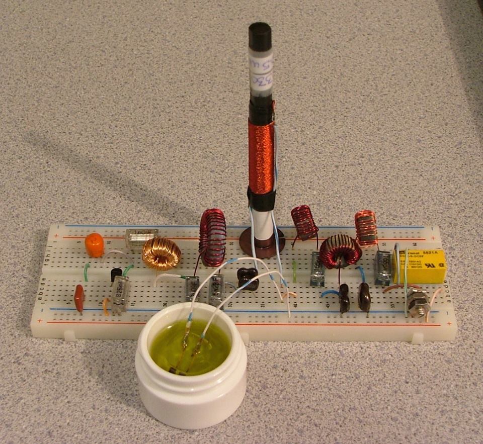
Amazing as this may sound, some of the electronic components used to make the Super Islander Mark IV transceiver came from the circuit boards of broken or damaged Compact Fluorescent Light Bulbs... and that means that there is virtually an endless supply of those parts.

Here is now amigo Bruno, and amigos listening to the program at this moment, a brief description of the Super Islander's Mark IV receiver module.

It starts with a simple resistive signal attenuator that feeds a dual tuned bandpass input filter.

The filter has a limited bandwidth , chosen so as to limit response to out of band signals... The filter is followed by a cascode transistor radio frequency amplifier stage, that feeds a broadband four diodes product detector.

Low level audio from the product detector goes to the audio filtering and amplifying module, made with discrete transistors, of which several of them are also recycled from the Compact Fluorescent Light Bulbs circuit boards...

This version of the Super Islander, the Mark IV , is radically different from any previous ones, as we have now switched over to a totally low cost solid state design , that can be easily reproduced because it uses very common electronic components and straightforward , easy to adjust circuits.

In our upcoming mid week edition I will describe the VFO, or variable frequency oscillator and the transmitter module of this unique low cost amateur radio transceiver, the Super Islander Mark IV... about the lowest possible cost transceiver that will make possible regular two way ham radio contacts on the 40 meters band using either voice or radiotelegraphy modes.

Saturday, March 5, 2016

AA1TJ -- On the Air with a Tuning Fork Transmitter using the 2,212th Harmonic and Olive Oil Cooling

The saturable magnetic frequency septupler. The tiny computer memory core is submerged in olive oil (Italian...naturalmente).


Not a very good picture, but here's the 1600Hz tuning-fork, fork oscillator, SRD pulse generator, PLL S/H phase-detector (diode gate), differential amplifier D.C. amplifier, and part of the 500kHz VCO.


The Wizard (AA1TJ) reports from the Hobbit Hole:

I was pleased to have made the first contact with my tuning-fork transmitter this evening. My contact, N1QLL, runs a pretty B&B on the Maine seacoast, midway between Bar Harbor and Cutler. Jerry was operating a solar-powered QRP station.  I found a follow-up email from him when I came up to the house for dinner. He's asking for a better explanation of my set-up. I can't wait to tell him about the passive frequency septupler made from an East German computer memory core, heat-sinked in a thimble of olive oil. 

My signal was also logged by a number of automated "Reverse Beacon Network" receivers (image attached) located in Ohio, North and South Carolina, Virginia and Pennsylvania...not bad for 90mW on 80m. Please note that my operating frequencies, 3,528.0 and 3,539.2kHz, are the 2,205 and 2,212th harmonics, respectively, of my 1,600Hz tuning-fork frequency reference.
FYI: the third attached image illustrates the block-diagram and tuning-fork reference oscillator circuitry for three common-wavelength AM broadcast transmitters operating in Berlin, Stettin and Magdeburg, Germany from 1928 through the mid 30's. A central 2,000Hz tuning-fork generated reference carrier was transmitted by landline to transmitters in the aforementioned cities whereupon the 529th harmonic was generated, amplified and broadcast at 1,058kHz. The equipment was designed by the Berlin-based firm, C. Lorenz A.G.. The fourth image details Lorenz' technique of frequency multiplication via saturable magnetic iron-core inductors. My septupler operates in an identical fashion.
A very pleasant day...


Mike points out that this is a work in progress.  He hopes to cross the pond (the Atlantic!) soon. Here is a update from Mike:

A nasty cold has delayed work on the 20 meter implementation, although some of the time I've spent crashed on the sofa was put to use redesigning the loop filter network. I think yesterday might have been my "hump" day so I'm looking forward to getting in some quality bench-time over the weekend. 

By the way, my PLL-based transmitter frequency stabilizing circuit has much in common with a garden-variety frequency-synthesizer. Obviously, the tuning-fork frequency reference is the main point of departure. My sampling phase detector, for example, was old hat by the mid-1960's. Nevertheless, this has been a fun project.

Sunday, February 14, 2016

"QSO Today" Podcast Interview with Michael Rainey AA1TJ

Picture

Eric 4Z1UG has a really great interview with Michael AA1TJ:


I listened to it as I aligned my HQ-100 receiver and worked on a digital frequency readout for the old receiver.   The interview was the perfect accompaniment for such a project.  Inspirational stuff.  Lots of great info on QRPp and homebrewing.  Mike talks about some of his more famous rigs including the voice-powered New England Code Talker (pictured above).  

I loved the story of Michael carting his DX-100 home in a wagon.  And I really sympathized when he described the harsh reaction of the phone operator to his early efforts at voice modulation.

Strongly recommended!   You won't be disappointed.  Great interview.  Thanks to Eric and Mike.


Saturday, February 6, 2016

Michael's Log: AA1TJ Has FIVE Contacts with the Unijunction Transistor at 1-2 milliwatts

Michael writes:

Dear Friends, The UJT transmitter circuit was improved considerably today. The power output has increased to 1.48mW and the start-up "whoosh" is now far less objectionable. It's currently running in beacon-mode at 3687.8kHz. I'll resume "CQing" as soon as I've returned from an hour's walk in the woods. I hoping to work K1QO among others. 73, Mike

Added five QSOs today. Seabury/AA1MY is in Maine...exactly 100 miles from my doorstep. It's wild to think that we made a one-hundred mile radio contact on a unijunction.

Tuesday, April 15, 2014

AA1TJ Crosses the Pond with 10 milliwatts


From a Facebook Post by Mike, AA1TJ:

Made 7 contacts with this tiny transceiver on 20m CW today with an RF output power of 10milliWatts. Five were stations in Georgia (GA QSO Party). The 6th was a regular QSO with a guy in Mississippi.
I answered a DX station calling CQ at 2230Z. Hearing nothing in response, I sent my call sign a half-dozen times anyway. More silence. As I was reaching for the knob to QSY he suddenly returned my call! ...Carlos, CT1BQH northeast of Lisbon, Portugal (that's him in the second photo). I was only 329 on his end but we kept it going for three minutes!
FYI: the transmitter (top circuit board) begins with a 3.58MHz ceramic resonator VXO (a 2N706 from the early 60's). That drives a push-push frequency doubler built around another 1960's-vintage, 2N2644 (obsolete stock from atop Mt. Mansfield, kindly given to me by Rich at Vermont Public Television). On receive, the 7MHz energy is routed via a DPDT relay (the orange rectangle) to the sub-harmonic (Polyakov) mixer located on the lower board. One stage of AF amplification is provided by a 2N333 that came off the GE assembly line in November of 1958. The DPDT relay is keyed directly. On transmit the 7MHz energy feeds a second push-push frequency doubler to produce 10mW at 14MHz (all spurs -35dBc, or less, with only the output resonator). The relay also switches the antenna between the transmitter and receiver.
Gosh, that was fun!

CT1BQH

Our book: "SolderSmoke -- Global Adventures in Wireless Electronics" http://soldersmoke.com/book.htm Our coffee mugs, T-Shirts, bumper stickers: http://www.cafepress.com/SolderSmoke Our Book Store: http://astore.amazon.com/contracross-20

Saturday, April 20, 2013

AA1TJ Crosses the Pond using an Electric Razor!

Take a look at Michael's Razor Rig, made from parts salvaged from his electric razor.   I was thinking that perhaps on the receive side a fox-hole receiver made with a rusty Gillette blade would fit in nicely with the shaving theme.   Very glad to see the AA1TJ blog getting more active. 

http://aa1tj.blogspot.com/2013/04/talking-to-france-via-my-electric-razor.html


Our book: "SolderSmoke -- Global Adventures in Wireless Electronics" http://soldersmoke.com/book.htm Our coffee mugs, T-Shirts, bumper stickers: http://www.cafepress.com/SolderSmoke Our Book Store: http://astore.amazon.com/contracross-20

Wednesday, March 27, 2013

AA1TJ's Latest QRPp Rig

 
From Mike, AA1TJ:

I called CQ on 20m CW for a couple of hours yesterday afternoon with no response. With the cadence of my own Morse tugging at my eyelids, I was suddenly shaken awake by a brisk signal returning my call and signing CU2BV. I snapped out a 579 report and turned it over. The dits and dahs in my headphones told me it was Fernando; operating from São Miguel island in the Azores. He reported a weak but solid copy (529) of my fifty milliwatt signal.

Here's the radio that I used yesterday. The one-transistor transmitter is to the left of the red relay on the top board. The single transistor is a germanium surface-barrier device made by Philco in August of 1958. To the right of the relay is a two-transistor time-delay circuit used to switch the antenna between the transmitter and the receiver. My receiver on the lower proto-board is a reproduction of my first shortwave receiver: a $7 Japanese kit that I bought at Radio Shack when I was 13 years-old.

Fifty milliwatts is some twenty-four times less power than was used by an old double D-cell flashlight. I later learned that my signal was nearly simultaneously picked up by an automated receiver located just west of Dusseldorf, Germany.

Snowy Vermont to the lush Azores - some 1500miles off the coast of Portugal - with less power than is consumed by a beeswax candle...is it any wonder that I love radio? ;-)


Our book: "SolderSmoke -- Global Adventures in Wireless Electronics" http://soldersmoke.com/book.htm Our coffee mugs, T-Shirts, bumper stickers: http://www.cafepress.com/SolderSmoke Our Book Store: http://astore.amazon.com/contracross-20

Saturday, March 16, 2013

Vanguard!


Wow, Vanguard even looks like a QRPp satellite. 

I suspected that something was up:  I noticed that Mike Rainey, AA1TJ has recently been crossing pond with a QRPp Germanium rig...  Then Steve "Snort Rosin" Smith clued me in: The next period of  Vanguard QRPp Activity Days begins tomorrow.  "Club 72" has a nice write up, and a nice collection of pictures of the Vanguard rigs that have been built around the world:

http://www.club72.su/vanguard.html

Go Germanium!  Go Vanguard!

Our book: "SolderSmoke -- Global Adventures in Wireless Electronics" http://soldersmoke.com/book.htm Our coffee mugs, T-Shirts, bumper stickers: http://www.cafepress.com/SolderSmoke Our Book Store: http://astore.amazon.com/contracross-20

Friday, November 2, 2012

The Hobbit Hole of QRP

In SolderSmoke 147 I mentioned that I had found some old pictures of AA1TJ's underground hamshack and workshop.  People wrote in asking me to post them.  Here they are.  I still can't find the shot of the door surrounded by snow. 


Our book: "SolderSmoke -- Global Adventures in Wireless Electronics" http://soldersmoke.com/book.htm Our coffee mugs, T-Shirts, bumper stickers: http://www.cafepress.com/SolderSmoke Our Book Store: http://astore.amazon.com/contracross-20


Friday, October 5, 2012

Sputnik Party 2012 Soapbox

Poster by Steve "Snort Rosin" Smith

3 October from AA1TJ:

Here's an admittedly late reminder that the Sputnik Party begins

tomorrow (4 October). I've been preoccupied with non-hobby concerns in
recent months but I did manage to throw something together for the
event.

My transmitter follows the lines of the 10mW, battery-powered, RF
beacon that was carried into orbit in 1958 by "Vanguard 1." You may
recall this is the one Premier Nikita Khrushchev characterized as "the
grapefruit satellite."

My present build uses essentially the same circuitry and componentry
as did an earlier, 20m version; details of which can be found at

http://aa1tj.blogspot.com/2012/06/vanguard-1-satellite-transmitter.html

The 15m version drives a 44m end-fed wire with 30milliWatts.

The receiver that I built for the event is essentially a "Q-multiplier
-> detector" type regenerative job. However, the Q-multiplication is
accomplished by a parametric amplification using a quartz-crystal
controlled pump. I thought it would be historically appropriate given
that parametric amplifiers were all the rage in the late 1950's.

I put together the keying and R/T changeover circuitry this morning.
When it appeared that "all systems were go" I began sending CQs on
21.060MHz. The band, or at least that portion of the band (the
receiver only tunes from 21.060 to 21.064MHz), seemed rather quiet,
but my 6th call netted a "dit dit dah dah dit dit." Resending my call,
I was very pleased to hear HB9DCL come back to me from just outside of
Zurich. The reports were 579/339. Frank was running 5W to a log
periodic antenna. I sure hope this is a sign of things to come!

I hope to be at the key by 1300Z tomorrow. Although my little
"grapefruit" only puts out 30mW, folks running "Sputniks" made from
ex-Soviet subminiature "rod tubes" should be at least two S-units
stronger. A number of European stations will be operating this year
and at least one station that I know of will be QRV from Japan. Just
listen for the beeps and give them a call!

Thank you,
Mike, AA1TJ

.......................


04/10/12  ( first day)
dear friends &Sputnikers
today a Belgian "sputnik clone" crossed the pond
first hit
15:22 with N0UR a 2 x sputnik "solid" QSO
Jim wrote: Thanks QSO, here is how you sounded in MN
( in attach)
16:00 second hit with AA1TJ , Mike "the inventor of all this Sputnik madness" hix 3 
this time a bit more difficult but at last we could manage to exchange reports,
between the QRM and noise at last got confirmation , 
Mike's sigs  here where 339 but still copyable
all OK with my 559 sigs then suddenly some other sputnikers came on the scene and I lost Mike
nevertheless
with my 60 years again excited as a young boy
as we made some history today hi x 3
will take a picture
for the moment a complete mess as the DC/DC invertor inside the sputnik  broke down
lost the very early contact with UA1CEG suddenly no more power in the SPUTNIK-cabine LOL
had to drag my new testbench power supply (still under construction )
or  lot of things to fix for those lausy 700 milliwatts hahahaha
73 to all
Jos
ON6WJ

.................................

News flash...Sputnik worked Vanguard across the pond. I just sent this
letter to some of the guys

Dear Friends

I won't forget this morning's QSO with ON6WJ anytime soon! As he
beeped/called CQ I could hear him riding on waves of QSB. I kept
hoping he would end on the top of the wave. It happened one time and
Jos sent "AA1TJ?" but by the time I re-sent my call we were back in
the trough of the wave. He started calling again and once again I
crossed my fingers. Finally it happened, he ended on top of a
particularly strong peak...and sure enough, he copied my callsign. It
took more effort to exchange the reports but we eventually did it! He
confirmed my 559 and I did the same for my 339 report. It must be true
that anything worthwhile doesn't come easy, because the more difficult
the QSO the more I seem to enjoy it! I copied Jos' info: "SPUTNIK PWR
700mW = ANT 3EL YAGI" perfectly on my tiny receiver. Just as amazing,
he copied my 30mW transmitter made from one PNP Germanium transistor
dating from September of 1959. Needless to say, I'm a happy camper
today. Merci Beaucoup, Jos.

Just above my operating frequency I heard PA0PJE sending "CQ Sputnik."
You had a beautiful signal here, PJ! It was easily S6 on the peaks. My
transmitter frequency trimmer adjustment is buried in a rat's nest of
wires which I didn't dare stick my hand in so early in the day.
However, if I hear you again I will definitely risk it.

Thanks Carlo/IZ4KBS and congratulations on your Russian QSO. Any
contact all with this simple stuff is reason for a celebration!

...and now back to the Hobbit Hole for another dose of QRPp.

73/72,
Mike, AA1TJ


Our book: "SolderSmoke -- Global Adventures in Wireless Electronics" http://soldersmoke.com/book.htm Our coffee mugs, T-Shirts, bumper stickers: http://www.cafepress.com/SolderSmoke Our Book Store: http://astore.amazon.com/contracross-20

Wednesday, July 4, 2012

AA1TJ -- As always, in the Vanguard

Here is a recent e-mail exchange between Michael, AA1TJ, and Dale, W4OP.  (Dale happens to be the fellow who built the W1FB Barebones Superhet that I am currently using on 17 meters. Details on this caper appear in SolderSmoke -- The Book). 


----------------------------------------------------
From AA1TJ: 


Wahoo...Dale, you amazing!

You are my first QSO with the Vanguard 1 reproduction satellite beacon transmitter. My circuit is a fairly close copy of the one shown on the lower left-hand corner of the 1959 CQ Magazine article (notice the output signal pick-off shown in this schematic is incorrect, or at least incomplete). My circuit uses link-coupled output impedance matching, which is similar to the only other documentation that I was able to dig up. The attached image "Early_Microlock_Bcn.jpg" was snipped from an original NASA report on the transmitter used in early airborne and sub-orbital tests leading up to the Vanguard flights. 


Yes, you heard correctly. I'm using a Philco 2N504 surface-barrier transistor, but please let me back up a bit. 

Roger Easton (a native Vermonter...and still resides here!) was at the helm of the communications development for the Vanguard/Minitrack project. Of the Vanguard "grapefruit" satellite beacon transmitters, he wrote in the May 2008 issue of High Frontier magazine

"We tried subminiature tube transmitters first. They worked marginally. Finally, Bell Telephone/Western Electric developed a very nice transistor for the task, and the problem was solved." 

However, that leaves out a small detail. They first tried Philco surface-barrier transistors, which worked fine on the bench, however two problems were discovered. They were found to be too temperature sensitive; the RF output power from the one-stage transmitter dropped excessively at elevated temps. Secondly, there was some issue with the packaging that produced erratic operation when the transistor was rotated positionally. The Western Electric devices proved better on both counts. 

The WE transistor appears to be "unobtainium" these days. That, plus the fact that my circuit won't be flying up to space anytime soon, prompted me to settle on a Philco 2N504. Although my device was manufactured in September of 1959 (Vanguard TV-4 - re-Christened "Vanguard 1" - first orbited on March 17, 1958), the 2N504 was an off-the-shelf item on the launch-date.

The only other obvious difference is the Vanguard 1 beacon circuit operated on 108MHz, whereas mine is presently working on 14.0596MHz. I recently had it running as a beacon on 10m for 48 hours but I had no luck given present band conditions.

The receiver is a simple, 0-V-0 regenerative set using a single Raytheon QF721 (fabricated in February 1953). I heard little activity on 20m when I started up my auto-keyer this morning. I had it looping 3X1 CQs whilst I worked on another project. To make matters more difficult, the exhaust fan was running in my shop and it happened to be raining heavily when you called. Worse yet, the receiver had drifted off my calling frequency by the time you called. I barely discerned a high-pitched CW "1" or "J"...which prompted me to quickly switch off the fan and re-tune. You were subsequently a solid 579. 

Of course my heart jumped when I heard you calling me...how I love that feeling! And it was a fabulous QSO so far as I'm concerned. Following our contact I opened my metal index card file box and pulled out the QSL that you sent to me following our "Code Talker" QSO. To think I now have another happy memory to add to that one! Thank you once again, Dale. It figures you'd be the one to pick-off my unannounced presence on the 20m QRP calling frequency with 25mW. Well done, OM. 

Also, you might enjoy this video of the actual launch, including some interesting control room audio banter. It may be found here: http://www.nrl.navy.mil/vanguard50/index.php. The way at least one of them nervously repeats, "Keep going baby!" gives some indication of the pressure these guys were under...having failed so spectacularly on two previous occasions. 

All the best,
Mike, AA1TJ    
        

On Mon, Jun 25, 2012 at 11:51 AM, Dale Parfitt wrote:

Hi Michael,
That was fun!
I first heard you on my SG-2020 rig, but did not have a paddle handy, so I fired up the K3. I don't ever recall having QRN on 20M, but it was  bad. Without it, you were 579 and even with it, 569 towards the end of the QSO.
I just happened to be QRV on 060 listening when I heard your CQ's. Not bad for a 25mW signal from (I think you said) a Philco transistor.
73,
Dale W4OP


Our book: "SolderSmoke -- Global Adventures in Wireless Electronics" http://soldersmoke.com/book.htm Our coffee mugs, T-Shirts, bumper stickers: http://www.cafepress.com/SolderSmoke Our Book Store: http://astore.amazon.com/contracross-20

Wednesday, May 2, 2012

Kick Panel Progress; Podcast Delay


I'm kind of behind on podcast production, but once again I have a good excuse:  I've been melting solder.   I decided to finally finish the Kick Panel DSB rig that I started building back in London.  It is built on a kitchen cutting board purchased in a Dyas store in Windsor.  The cabinet is fashioned from an aluminum kick panel for a door (a pub door!).   

I originally intended this to be just a transmitter (for use with my trusty Drake 2-B) but it is so easy to add a direct conversion receiver to a DSB rig that I just threw together a version of the NE-602 LM386 Neophyte receiver and hooked it up to the 75 meter VFO.  It sounds great.  I love DC receivers. They seem to connect you directly to the ether. And now I'll have a complete 75 meter DSB station in one box.

This morning I tested the balanced modulator (singly balanced with two diodes).  DSB is being generated.  All I have to do now is put a little 6 db pad between the modulator and the amplifier chain, then work on the antenna a bit and I should be on 75.  The amplifier chain dates back to the period when Mike, KL7R, and I were using LTSpice to design amps....

I was very pleased to include in this rig a part that Michael, AA1TJ, sent me:  I have a little 10.7 MHz IF can in the front end of the RX.  A cap allows it to tune in 75 meters. Thanks Mike!

I hope to get a podcast out this weekend (if the computers cooperate -- the Sony Vaios "light bulb-repaired" laptop finally gave up the ghost last weekend.) 

Our book: "SolderSmoke -- Global Adventures in Wireless Electronics" http://soldersmoke.com/book.htm Our coffee mugs, T-Shirts, bumper stickers: http://www.cafepress.com/SolderSmoke Our Book Store: http://astore.amazon.com/contracross-20

Thursday, February 9, 2012

The Parasaki: DL3PB's Amazing All Diode Transceiver

JBOD! FB!


Hi folks,


I'd like to share with you a long-cherished dream, that recently came true, forty years after I came to read about hams using tunnel diodes to make QSOs when I was aged twelve or so:


Finally I managed a first skywave QSO with my PARASAKI-transceiver, an 'all diode' rig: Christophe/F8DZY replied to my very first call on 20m band in REF-contest last weekend. I was running 2mW into a temporary vertical dipole on my balcony. Distance between us is 918km - obviously OM Christophe has excellent ears.


Those interested in the cruel details of my circuit, please find attached a schematic and a photo of the pretty ugly setup. The circuit is designed straight-forward with exception of the parametric VXO, derived from Mike/AA1TJ's famous Paraceiver design. (see http://fhs-consulting.com/aa1tj/paraceiver.html )


The low impedance of the high peak-current tunnel diodes make it very difficult to built a really crystal controlled oscillator rather than an LC-oscillator, synchronized by the crystal more or less, at least on the higher SW-bands. The Parametric VXO provides a crystal-stable, chirp-free signal on expense of an output power of two milliwatts only instead of ten, but with an amazing spectral purity, no need for a low pass filter or such. Of course it sounds pretty cool making a QSO with a 'bunch of diodes' and a parametrically excited crystal, but believe me or not, I'd preferred to bring that full ten milliwatt into the air - on the other hand that approach allowed to tune the rig a bit ( ~ 5kHz/per xtal), which turned out to be much more valuable than a few milliwatts more while being 'rock-bound'.


The receiver in its 'gain-less' version works fine for strong signals - while listening to QRP(p) stations, the moderate gain of the audio amplifier helps a lot. A comfortable frequency shift between receive and transmit is realized by the 5µH inductor at the LO-port of the mixer, with little effect on sensitivity.


Thanks for the bandwidth, OMs, won't bother again you with such mails, unless I make a cross-pond QSO with that rig ( not that likely ) or any skywave QSO with homemade semiconductors ( probably impossible )...


72!


Peter/DL3PB


Our book: "SolderSmoke -- Global Adventures in Wireless Electronics"http://soldersmoke.com/book.htmOur coffee mugs, T-Shirts, bumper stickers: http://www.cafepress.com/SolderSmokeOur Book Store: http://astore.amazon.com/contracross-20

Saturday, December 17, 2011

"The Little Sweetheart" Receiver

Wow, what a beautiful piece of work! And a fascinating story behind it, with hints of wartime romance... Thanks to Mike AA1TJ whose very eclectic reading (Czech tech mags!) led us to this. Thanks also the Crypto Museum. Here is the link:

http://www.cryptomuseum.com/spy/sweetheart/index.htm

With more info here:
http://antiqueradios.com/forums/viewtopic.php?t=96007
And here:
http://antiqueradios.com/forums/viewtopic.php?t=96057


Our book: "SolderSmoke -- Global Adventures in Wireless Electronics"http://soldersmoke.com/book.htmOur coffee mugs, T-Shirts, bumper stickers: http://www.cafepress.com/SolderSmokeOur Book Store: http://astore.amazon.com/contracross-20

Saturday, November 5, 2011

21st Century Ham Radio -- EDN Article

A few listeners sent this in. Thanks! Note the mention of AA1TJ's CFL light bulb rig!

http://www.edn.com/article/519742-Ham_radio_in_the_21st_century.php


Our book: "SolderSmoke -- Global Adventures in Wireless Electronics"http://soldersmoke.com/book.htmOur coffee mugs, T-Shirts, bumper stickers: http://www.cafepress.com/SolderSmokeOur Book Store: http://astore.amazon.com/contracross-20

Tuesday, October 4, 2011

Sputnik!!! SolderSmoke 138!!!

Today is Sputnik Anniversary Day! Michael, AA1TJ, and his intrepid international band of solder melters will be putting their homebrew Soviet-parts rigs on 15 meters! I will be listening with my HQ-100. This is all discussed on SolderSmoke 138, which I have just uploaded:

http://soldersmoke.com/soldersmoke138.mp3

October 4, 2011
A Meteor and Jupiter: Cosmic Birthday Present!
Sagan's Pale Blue Dot -- Lots of interesting radio info
On the cover of "Hot Iron"!!!!
The HW-7 Philosophy and Way of Life
Sputnik Anniversary
Getting my 2B back on 17
Preparing for a return of sunspots and 17 meters
Raiding Radio Shack (for 2N2222s!)
The Autumn SPRAT
MAILBAG

Our book: "SolderSmoke -- Global Adventures in Wireless Electronics"http://soldersmoke.com/book.htmOur coffee mugs, T-Shirts, bumper stickers: http://www.cafepress.com/SolderSmokeOur Book Store: http://astore.amazon.com/contracross-20

Friday, September 30, 2011

Oscillating Light Bulbs

Oh man, this is some fascinating stuff: old light bulbs found to be oscillating at VHF! Wayne, VA7AT, stumbled upon this phenomenon at age 13 while engaged in Knack activities. Now Joe Sousa explains the physics behind the emissions that caused Wayne's light bulb to interfere with the broadcast of baseball games. How long until AA1TJ has one of these bulbs on the air, making contacts? There is much in this that would appeal to Michael: light bulbs, weird physics, translations from German... You gotta love the BNC connector plugged directly into the bulb. Check it out the radio museum article here.

Hi Bill
There was a question posted on Antennex E-mail discussion group talking about how a vacuum type light bulb will oscillate and radiate RF at about 100MHZ. This answered the question I had since I was a boy of 13 experimenting with a light bulb in series with an electrolysis bath (aluminum electrodes with table salt dissolved in water) and 117vac. The bulb dimmed with the electrodes apart and at a certain position the radio I had on blanked out with fissing sound. I had to shut down the experiment quickly because the neighbors were listening on their favorite baseball game and cussed loudly .

I now know what happened on that fateful day. Here is a site I found about the oscillating light bulb http://www.radiomuseum.org/forum/rustika_lightbulb_fm_measurements.html
Wayne VA7AT

Our book: "SolderSmoke -- Global Adventures in Wireless Electronics"http://soldersmoke.com/book.htmOur coffee mugs, T-Shirts, bumper stickers: http://www.cafepress.com/SolderSmokeOur Book Store: http://astore.amazon.com/contracross-20

Thursday, September 29, 2011

Sputnik Rigs Cross the Pond, Cambridge to Cambridge

The Chief Designer, Michael, AA1TJ, alerted us to this wonderful post on Roger, G3XBM's blog:
http://g3xbm-qrp.blogspot.com/2011/09/sputnik-across-atlantic-today.html
We clearly see the spirit of the International Brotherhood of Electronic Wizards in Roger's comment: "Nice to think that valves used in missiles aimed at each other in the Cold War end in bringing friendship and joy. CW is a wonderful mode if you want simple equipment capable of DX." Indeed. Well done!


Our book: "SolderSmoke -- Global Adventures in Wireless Electronics"http://soldersmoke.com/book.htmOur coffee mugs, T-Shirts, bumper stickers: http://www.cafepress.com/SolderSmokeOur Book Store: http://astore.amazon.com/contracross-20

Tuesday, July 19, 2011

Royal Order of the Sputnik Clone Chasers

Kettering Group, UK

From the Chief Designer (AA1TJ):

Fellas,

I came across an online blurb for the recent book, Sputnik: The Shock of the Century, by Paul Dickson; a worthwhile read, judging from the introduction and first chapter.

http://www.sputnikbook.net/intro.php

"Someone brought out a shortwave radio, and soon a beeping noise filled the room. A Russian scientist, Anatoli Blagonravov, confirmed it was Sputnik. "That is the voice," he said dramatically. "I recognize it." John Townsend Jr., one of the scientists at the party, recalled watching Blagonravov: "I knew him quite well, and I could tell that he was a little surprised and quite proud. My reaction was 'Damn!'"

And so an abstraction now had a voice. It also had a name - Sputnik.

Many of those at the party adjourned to the Soviet Embassy's rooftop, attempting to view Sputnik with the naked eye. Several of the American scientists drifted over to the American IGY headquarters in Washington, where they began speculating on what impact the satellite would have. They feared that the American people would be disappointed.

It also dawned on them that they had better start tracking the satellite's orbit. They got in touch with the American Radio Relay League in West Hartford, Connecticut, asking its 70,000 members-all "ham" radio operators-to lend a hand and help track the Sputnik. In less than twenty-four hours, reports on the satellite were coming back to the National Science Foundation, where a temporary control room had been established. Eventually, these hams and other amateur and professional trackers would consider themselves part of a great international fellowship known as ROOSCH, or the Royal Order of Sputnik Chasers."

That's right guys...ROOSCH...the Royal Order of Sputnik Chasers. And to think that fifty four years later a second great international fellowship would rise from the ashes...ROOSCCH, or the Royal Order of Sputnik Clone Chasers! ;o)

(BTW, October 4, 1957 is an important date in American history for a second reason. On that evening the first episode of Leave it to Beaver made its debut.)

...............................................

I thought we should also at this point remember the intrepid lads of the Kettering Group, pictured above. (Some of those dudes look like they would have been right at home in "Leave it to Beaver.") For more info on their amazing Sputnik adventures go here:
http://www.svengrahn.pp.se/trackind/getstart/oldcyts.htm
and here
http://www.svengrahn.pp.se/trackind/trackin1.htm#KEttrack


Check out "SolderSmoke -- Global Adventures in Wireless Electronics"
http://soldersmoke.com/book.htm

Monday, July 18, 2011

Sputnik QSL from the Soviet IGY Committee

I like the reminder of Sputnik's IGY connection. This is from an article by John Foley. W7ETS, in the October 2007 issue of QST. Be sure to read the translation in the caption.

Yesterday Billy and I were at the Smithsonian Air and Space Museum's Dulles Airport center. (We volunteer to take visiting relatives to the airport IF we get to go to the Smithsonian afterwards.) We checked for Sputniks. Nyet. I think they have one on display in the main Air and Space building.

I was thinking that listening to a signal from a spacecraft should be part of the Sputnik event. The packet 2-meter signals from the International Space Station are probably the easiest to receive these days.

Check out "SolderSmoke -- Global Adventures in Wireless Electronics"http://soldersmoke.com/book.htm
Designer: Douglas Bowman | Dimodifikasi oleh Abdul Munir Original Posting Rounders 3 Column